Caution – Wheatheart WHR 130 x 51-71ft Augers PTO User Manual
Page 30
3. A
SSEMBLY
WHEATHEART - GHR & WHR GRAIN AUGERS
3.10. L
IFT
C
YLINDERS
& C
ABLE
GRAIN AUGERS SD
30
30662 R1
3. Secure the solid connector end of the short cylinder connector hydraulic hose
to above elbow fitting on right side lift cylinder. Use thread sealant (not
supplied). The other end of this short hose is secured later.
4. Attach other lift cylinder to left side of welded bracket with four 7/16” x 1-1/4”
bolts and locknuts. Tighten securely (see Figure 3.11 for correct position).
Note:
Although the lift cables are factory installed on the lift cylinders, make certain the
cable clamps at the cylinder are secure and the cables are properly seated in the
cable sheaves before attaching the cable to the track shoe.
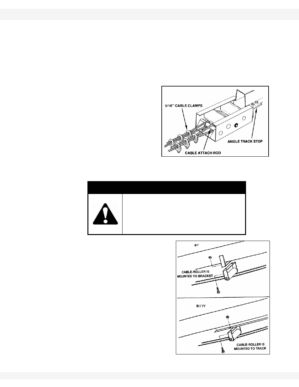
5. With
both
cylinders in full down
position and track shoe resting
against the track stop, thread
both cables over the cable
attach rod on the track shoe.
Pull cable very tight then secure
with three 5/16” cable clamps
on each cable, positioned as
shown in Figure 3.19. Tighten
securely. Tie up excess ends of
lift cable with tape or ty-wrap.
Lift cables will stretch with use.
Check frequently and adjust when necessary.
6. Attach
the
cable roller to the
appropriate location with two 7/16” x
1-1/4” bolts and locknuts (Figure 3.20).
• On the 61' auger, attach the cable
roller to bracket located between
lower end of track and lift cylinder
(see Figure 3.11 for location).
• On the 51'/71' augers, attach the
cable roller to lower end of track
(see Figure 3.11 for location).
CAUTION
Track shoe must rest against the track stop
when adjusting cable.
Failure to heed will allow auger to raise higher
than it is designed to lift, resulting in damage
to auger and injury to personnel.
Figure 3.19
Important:
Figure 3.20