Lift cylinders & cable, End of section 3.10 – Wheatheart WHR 130 x 51-71ft Augers PTO User Manual
Page 29
WHEATHEART - GHR & WHR GRAIN AUGERS
3. A
SSEMBLY
GRAIN AUGERS SD
3.10. L
IFT
C
YLINDERS
& C
ABLE
30662 R1
29
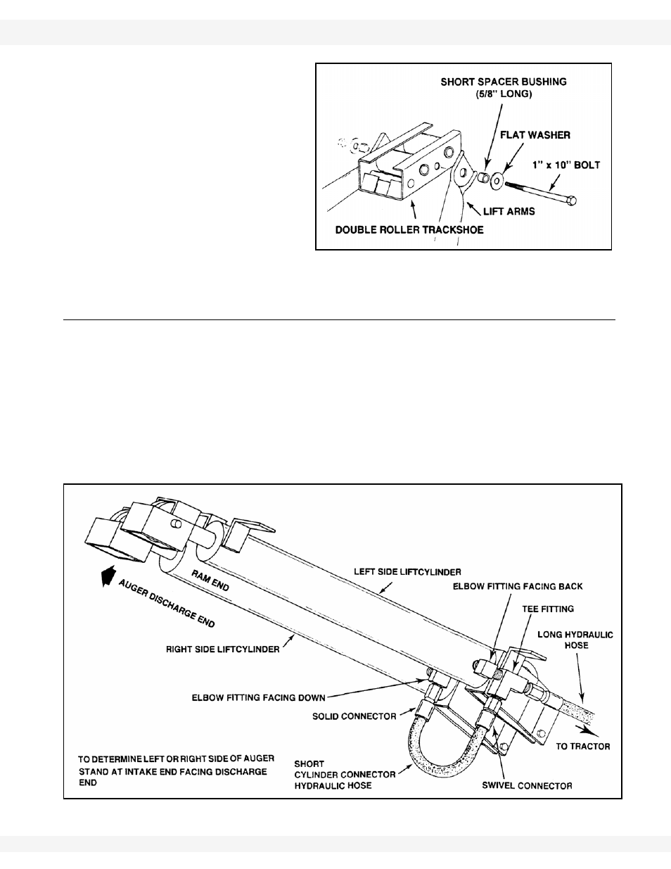
11. Attach upper lift arms
to track shoe. Use a
short spacer bushing
(5/8” long) and flat
washer on both sides,
insert the 1' x 10' bolt
and Tighten securely
with locknut (Figure
3.17).
12. Lower upper end of
auger slowly until the
roller track shoe rests
against the track stop.
3.10. LIFT CYLINDERS & CABLE
Note:
Determine right or left side of auger by standing at intake end facing top
discharge end.
1. Position one of the lift cylinders to right side of welded brackets on lower end
of auger tube (see Figure 3.11 for correct position). Attach with four 7/16” x
1-1/4” bolts and locknuts. Tighten securely.
Note:
Cylinder must be positioned with ram end towards discharge end of auger.
2. Rotate the elbow fitting at lower end of lift cylinder so it faces down, making
certain it is securely tightened (Figure 3.18).
Figure 3.18
Figure 3.17