Hydraulic power swing (option), Notice – Wheatheart X13 Power Swing User Manual
Page 17
W
HEATHEART
- P
OWER
S
WING
M
ANUAL
2. A
SSEMBLY
E
LECTRIC
AND
H
YDRAULIC
2.5. H
YDRAULIC
P
OWER
S
WING
(O
PTION
)
30802 R0
17
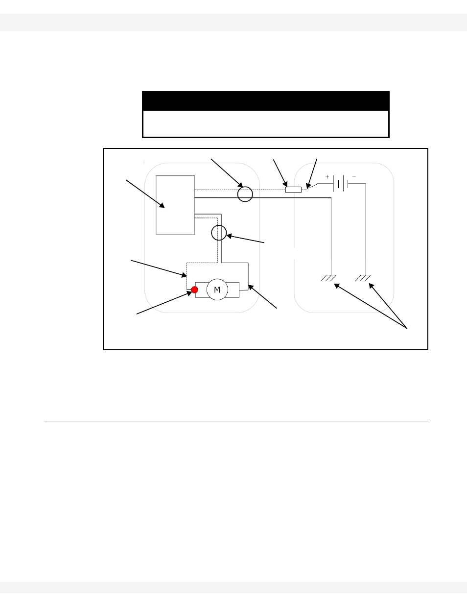
9. Attach the positive wire directly to the positive terminal on the tractor battery
and the negative wire to the tractor chassis as shown in Figure 2.10. The
negative terminal on the tractor battery should also be grounded to the
chassis. There are 5/16” lugged terminals supplied with the kit.
Figure 2.10 Power Swing Wiring Diagram
Note:
If the electric power swing will need to be moved from one tractor to another on a
regular basis, 200 Amp booster-style cable clamps can be installed at the
owner’s own risk and expense.
2.5. HYDRAULIC POWER SWING (OPTION)
1. Install the hydraulic control valve and top clamp assembly onto the swing
tube using a bottom 13” half-clamp and two 7/16” x 1-1/4” bolts (18698) and
locknuts (19598). This is to be installed approximately 24” up the swing tube,
from the top of the Power Swing clamp (see Figure 2.11).
2. Attach the two short 1/2” hydraulic hoses to the valve and the hydraulic motor
on the Power Swing (see Figure 2.11).
3. Install a half-clamp hose/wire retainer further up the swing tube, using two
7/16” x 1” bolts (19542) and locknuts (19598). Position half-clamp retainer in
best location, and tighten securely. See Figure 2.11.
4. Attach long 1/2” hydraulic hoses to the hydraulic valve.
5. Route these hoses towards tractor, through the clips on top of the half-clamp
retainer, and loop them around the spout head on the swing auger.
NOTICE
If these electrical cables are not hooked up properly the
electric controller will be damaged.
TRACTOR
POWER SWING
LONG ELECTRICAL CABLE
POSITIVE
WIRE
NEGATIVE WIRE AND TERMINAL
GROUNDED TO CHASSIS
POSITIVE WIRE
NEGATIVE
WIRE
RED
BOOT
RECEIVER
BOX
CIRCUIT BREAKER
SHORT
ELECTRICAL
CABLE