OSRAM SYLVANIA LED 2x2 Retrofit Kit User Manual
Page 2
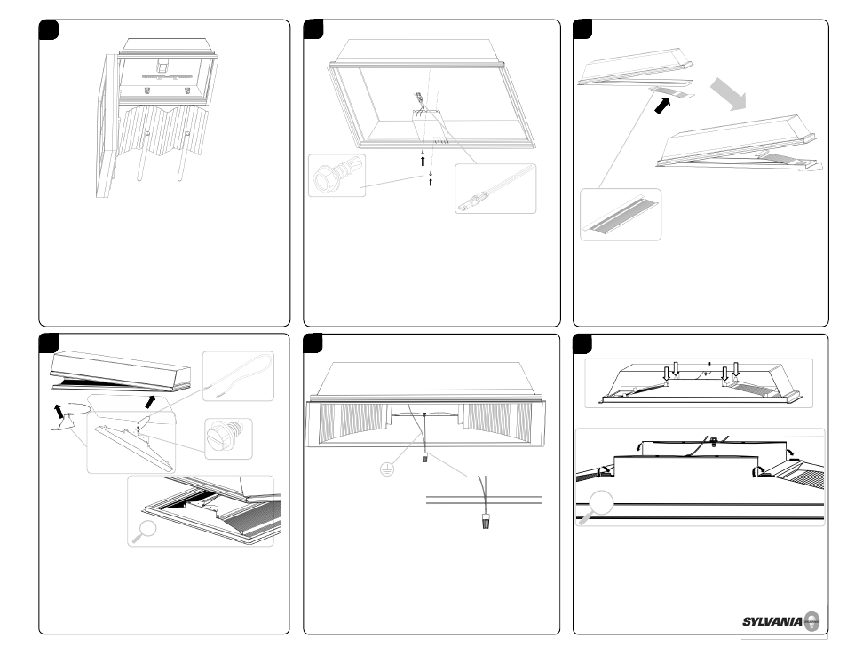
1
PREPARE EXISTING FIXTURE FOR INSTALLATION
REMOVE EXISTING:
LENS / LENS FRAME
PARABOLIC LOUVER
REFLECTORS / BALLAST COVERS
BRACKETS
LAMPS / LAMP HOLDERS
Prior to installation, remove all electrical parts and the
ballast compartment cover leaving only the supply and
grounding leads.
2
3
4
5
6
INSTALL LED DRIVER AND DRIVER DISCONNECT
DANGER—RISK OF SHOCK—DISCONNECT POWER BEFORE
INSTALLATION.
Using the provided self-drilling screws, properly affix specified
LED Driver to fixture. When drilling for installation of retrofit kit
hardware, please check for enclosed wiring and
components. Properly install Driver Disconnect to driver; black
to black and white to white.
NOTE: LED driver location will depend on troffer depth. The LED
driver may need to be off centered when installing in a
shallow troffer.
2X
INSTALL GROUND STRAPS & END BRACKETS
Remove PVC film from End Brackets before installing. Use
3/8” slotted screws to secure one end of the green ground
strap to the small hole found on End Bracket. Lift one end
of the existing fixture and place End Bracket between the T-
grid and the existing Fixture body. Position the Reflector
Bracket so that the slots on the Reflector Bracket mate with
the tabs on the End Brackets. Repeat the procedure for the
second End Bracket. DO NOT bend the tabs yet.
+
2X
INSTALL REFLECTOR BRACKETS INTO EXISTING FIXTURE
The LED Retrofit Kit is designed to rest between the existing
fixture body and the T-grid. Remove protective coating from
brackets before installing. Lift one side of the existing fixture
and place Reflector Bracket between the existing Fixture
body and T-grid . Lower the fixture body onto the Reflector
Bracket. Repeat procedure to install the second Reflector
Bracket.
2X
2X
2X
BEND TABS TO SECURE ASSEMBLY
GROUND & SECURE RETROFIT KIT INTO EXISTING FIXTURE
Bond the retrofit assembly to the existing fixture by
connecting a Green Ground Strap directly to mains ground.
With both Reflector Brackets and both End Brackets installed
and correctly positioned, secure the assembly by folding over
the two inner locking tabs applying finger pressure. The
remaining outer tabs are for alignment only. There should be
Four tabs in total that are folded over.
+