Exide Technologies GB4127 User Manual
Page 17
046-0372 Setup
12/9/09
047-0175 EXIDE REV04
Page
16
of
31
the desired setting (0: count down, 1: count up) and press ENTER to save it. If the direction is set to count down,
the battery ready light does not come on until the cool down time has elapsed. If the direction is set to count up,
the battery ready light comes on when the charge is complete and the elapsed time since the charge completed is
displayed.
2.2.3.6 Setting
Automatic
Refresh
To set the automatic refresh interval, press SET, then 5, then 8. The display shows ‘REFRESH TIME’ followed
by ‘AR:’ and the refresh interval time. Enter the desired interval for automatic refresh (00:00 to disable) and
press ENTER. A refresh consists of 30 minutes of charging at the equalize current.
2.2.3.7 Setting Charger Alerts
To set the alert parameter, press SET, then 5, then 0. The display shows ‘ALERT ENABLE’ followed by ‘AO:’
and the alert setting. Enter the desired setting (0: disable alerts, 1: enable alerts) and press ENTER. The display
shows ‘ALERT INTERVAL’ followed by ‘AI:’ and the alert interval in seconds. Enter the desired setting and
press ENTER. With alerts enabled, the control displays a message describing the charger state at the set interval.
2.2.3.8 Setting Automatic Start Mode
To set the automatic start mode, press SET, then STOP. The display shows ‘AUTO START MODE’ followed by
‘AS:’ and the automatic start setting. Enter the desired setting (0: manual start, 1:auto start, 2:auto start on AC)
and press ENTER. If manual start is set, the charger never starts automatically. When the battery is connected,
the display shows ‘CHARGER OFF’. Press STOP to manually start the charge. Also, in manual start mode the
charger does not begin a refresh or automatic equalize cycle once the charger has turned off. If auto start on AC is
set, the charger begins a new charge cycle whenever AC power is removed and restored to the charger. This is
useful in applications where the charger is permanently connected to the battery and a charge cycle is initiated by
plugging in the charger AC power cord.
2.2.4
Setting the Other Parameters
If the charger is part of an I’m Cool system or the TOBi
®
Battery Management System then the charger identifier
(ID) must be set. This and other additional parameters are programmed in a manner similar to that above. Table 1
describes the parameters and key-strokes used for programming them. When more than one parameter is in the
same row of the table, the control automatically sequences through the additional parameters.
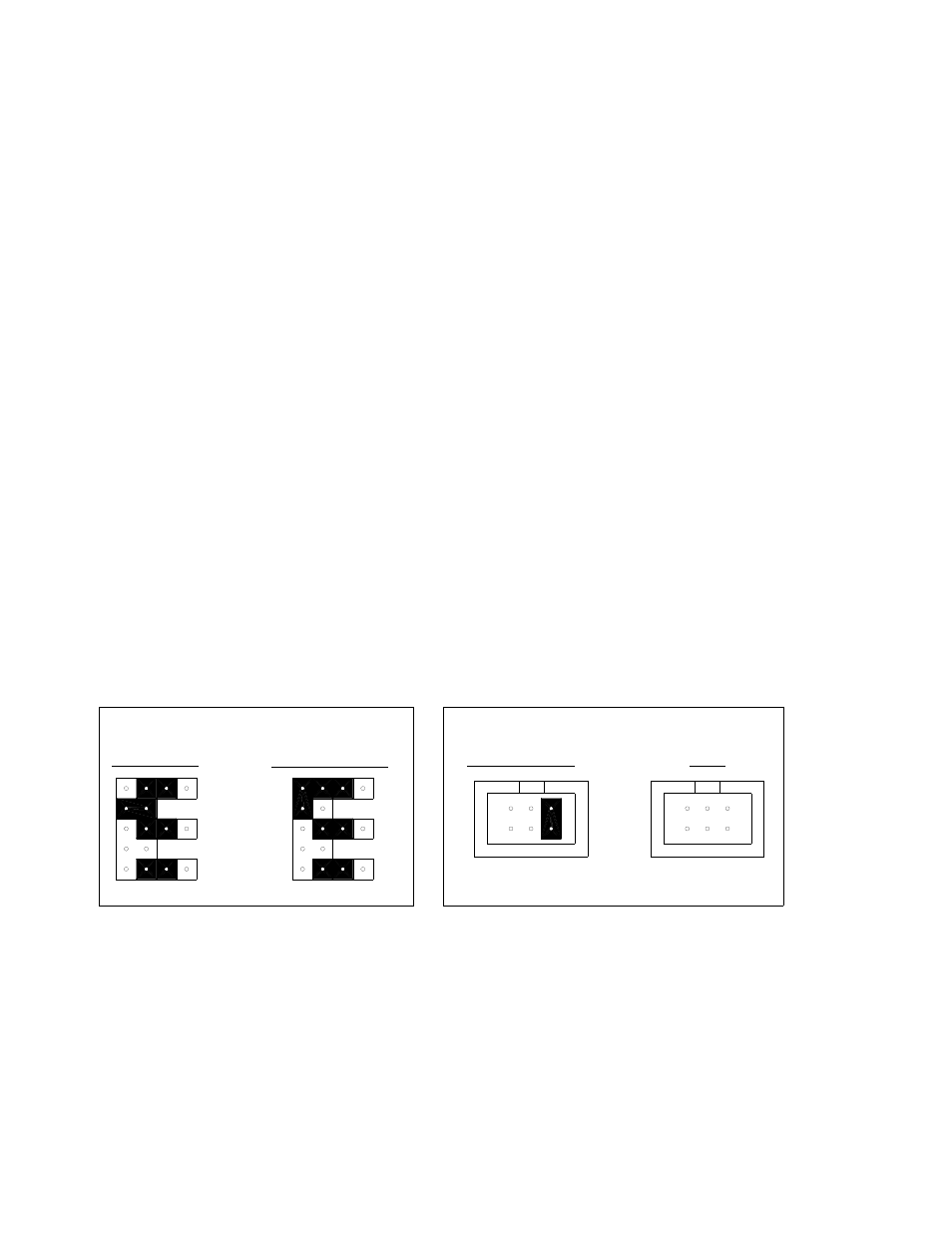
2.2.5 JUMPER
SETTINGS
Refer to figure 1 for jumper locations.
Jumper location J4 is used to lock or unlock certain parameters from programming mode.
Header J1 is used to select the charger type.
J4
LOCKED
UNLOCKED
J4
J1
PARAMETER LOCKOUT
CHARGER TYPE
FERRO/CF
HF*
J1
*J1 used for interface to HF module