CCI Thermal Technologies FX5 - Explosion-Proof Electric Air Unit Heater User Manual
Page 10
10
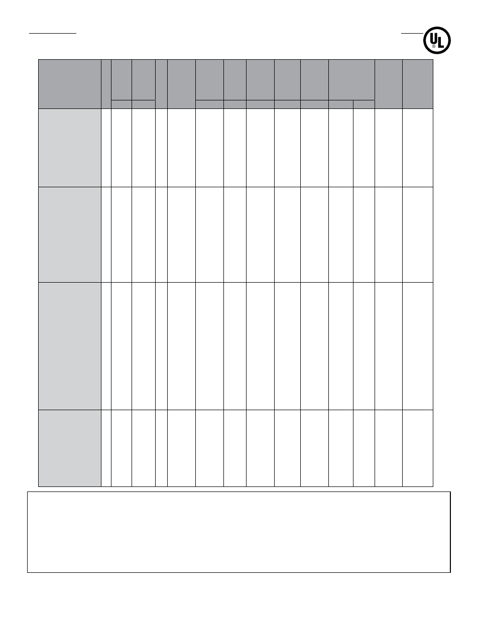
F X 5 T E C H N I C A L D ATA F O R 6 0 H Z
E L E C T R I C H E AT E R S
C US
Model
Note
V
oltage
Nominal
W
attage
Phase
Max. Motor Nameplate
Current
Heater W
attage
Total
Current
Minimum Circuit Ampacity
Supply W
ire
Maximum Fuse Size
Temperature
Rise
Core Kit
Part Number
Contactor
Part
Number
(V) (kW)
(W)
(A)
(A)
(AWG)
(A)
°F
°C
FX5-208160-030
208
3.0
1
2.7
2700
14.4
18.0
12
20
19.0 10.5 12116
10557
FX5-208160-050
208
5.0
1
2.7
4700
24.0
30.0
10
30
31.6 17.6 12117
10557
FX5-208160-075
208
7.5
1
2.7
7200
36.1
45.1
6
50
27.9 15.5 12118
10557
FX5-208160-100
* 208 10.0 1
2.7
9690
48.1
60.1
4
70
37.2 20.7 12119
10558
FX5-208360-030
208
3.0
3
1.4
2700
8.3
10.4
14
15
11.2
6.2
12116
10557
FX5-208360-050
208
5.0
3
1.4
4700
13.9
17.4
12
20
18.6 10.3 12117
10557
FX5-208360-075
208
7.5
3
1.4
7200
20.8
26.0
10
30
27.9 15.5 12118
10557
FX5-208360-100
208 10.0 3
1.4
9700
27.8
34.8
8
35
37.2 20.7 12119
10557
FX5-208360-150
208
15
3
1.4
14400 41.6
52.0
6
60
27.1 15.1 12120
10557
FX5-240160-030
240
3.0
1
2.7
2700
12.5
15.6
12
20
19.0 10.5 12122
10557
FX5-240160-050
240
5.0
1
2.7
4700
20.8
26.0
10
30
31.6 17.6 12123
10557
FX5-240160-075
240
7.5
1
2.7
7200
31.3
39.1
8
40
27.9 15.5 12124
10557
FX5-240160-100
240 10.0 1
2.7
9700
41.7
52.1
6
60
37.2 20.7 12125
10557
FX5-240160-150
* 240 15.0 1
1.4
14400 62.5
78.1
2
80
27.1 15.1 12126
10558
FX5-240360-030
240
3.0
3
1.4
2700
7.2
9.0
14
15
19.0 10.5 12122
10557
FX5-240360-050
240
5.0
3
1.4
4700
12.0
15.0
14
15
31.6 17.6 12123
10557
FX5-240360-075
240
7.5
3
1.4
7200
18.0
22.5
10
25
27.9 15.5 12124
10557
FX5-240360-100
240 10.0 3
1.4
9700
24.1
30.1
8
35
37.2 20.7 12125
10557
FX5-240360-150
240 15.0 3
1.4
14400 36.1
45.1
6
50
27.1 15.1 12126
10557
FX5-240360-200
* 240 20.0 3
1.4
19400 48.1
60.1
4
70
36.1 20.1 12127
10558
FX5-480160-030
° 480
3.0
1
1.3
2700
6.3
7.9
14
15
19.0 10.5 12129
10557
FX5-480160-050
° 480
5.0
1
1.3
4700
10.4
13.0
14
15
31.6 17.6 12130
10557
FX5-480160-075
° 480
7.5
1
1.3
7200
15.6
19.5
12
20
27.9 15.5 12131
10557
FX5-480160-100
° 480 10.0 1
1.3
9700
20.8
26.0
10
30
37.2 20.7 12132
10557
FX5-480160-150
° 480 15.0 1
1.3
14400 31.3
39.1
8
40
27.1 15.1 12133
10557
FX5-480160-200
° 480 20.0 1
1.3
19400 41.7
52.1
6
60
36.1 20.1 12134
10557
FX5-480360-030
480
3.0
3
0.7
2700
3.6
4.5
14
15
19.0 10.5 12129
10557
FX5-480360-050
480
5.0
3
0.7
4700
6.0
7.5
14
15
31.6 17.6 12130
10557
FX5-480360-075
480
7.5
3
0.7
7200
9.0
11.3
14
15
27.9 15.5 12131
10557
FX5-480360-100
480 10.0 3
0.7
9700
12.0
15.0
14
15
37.2 20.7 12134
10557
FX5-480360-150
480 15.0 3
0.7
14400 18.0
22.5
10
25
27.1 15.1 12133
10557
FX5-480360-200
480 20.0 3
0.7
19400 24.1
30.1
8
35
36.1 20.1 12134
10557
FX5-480360-250
480 25.0 3
1.0
24200 30.1
37.6
8
40
22.0 12.2 12135
10557
FX5-480360-300
480 30.0 3
1.0
29200 36.1
45.1
6
50
26.4 14.6 12136
10557
FX5-480360-350
480 35.0 3
1.0
34200 42.1
52.6
6
60
30.7 17.1 12137
10557
FX5-600360-030
600
3.0
3
0.6
2700
2.9
3.6
14
15
19.0 10.5 12138
10557
FX5-600360-050
600
5.0
3
0.6
4700
4.8
6.0
14
15
31.6 17.6 12139
10557
FX5-600360-075
600
7.5
3
0.6
7200
7.2
9.0
14
15
27.9 15.5 12140
10557
FX5-600360-100
600 10.0 3
0.6
9700
9.6
12.0
14
15
18.1 20.7 12141
10557
FX5-600360-150
600 15.0 3
0.6
14400 14.4
18.0
12
20
27.1 15.1 12142
10557
FX5-600360-200
600 20.0 3
0.6
19400 19.2
24.0
10
25
36.1 20.1 12143
10557
FX5-600360-250
600 25.0 3
0.8
24200 24.1
30.1
8
35
45.2 25.1 12144
10557
FX5-600360-300
600 30.0 3
0.8
29200 28.9
36.1
8
40
26.4 14.6 12145
10557
FX5-600360-350
600 35.0 3
0.8
34200 33.7
42.1
8
45
30.7 17.1 12126
10557
NOTES:
* Exceeds the 48 Amp Curcuit limit of NEC 424-22. DS5 not available for these units.
° 480 - 1 phase units are certified Class I, Div. 1, Group D and Class II, Div. 1 Groups F & G.
1. Minimum conductor size for 86˚F (30˚C) ambient. Derate conductor for ambient temperature. Use minimum 194˚F (90˚C) insulation.
2. Heater is functioning normally if at rated voltage the amp draw is within 10% of the value in this table.
3. Operation at lower voltages will result in reduced heat output and amp draw
4. Add "T" to model number when adding a built-in thermostat
5. Add "D" to model number when adding a built-in disconnect switch
6. Add "P" to model number when adding a built-in pilot light
7. Add "S" to model number when adding a 3-way switch
8. Add "H" to model number for units with high "off" (deenergized) ambient temperatures
9. Add "U" to model number for units with continuous fan option.
10. Add "A" to model number for units with stainless steel cabinet.