Clearances for maintenance, Piping applications – CCI Thermal Technologies HP - High Pressure Heat Exchanger Unit Heater User Manual
Page 5
5
4
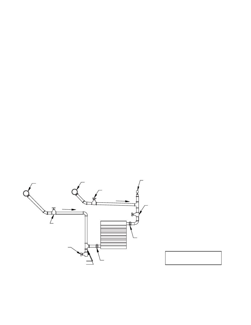
SHUT-OFF VALVE
PITCH DOWN
UNION
6 in. (152 mm) LONG
FULL SIZE
DIRT POCKET
RETURN
SUPPLY
PITCH DOWN
DRAIN VALVE
AUTOMATIC
AIR VENT
OR
PETCOCK.
SHUT-OFF VALVE
BALANCING
VALVE
UNION
Where heaters are installed in applications that are of a relocatable or transportable nature such as land or offshore drilling
rigs, an adequate mounting structure should be supplied to withstand all probable load conditions. Such load conditions
should recognize abuse situations such as truck off-loading impacts, etc. It is recommended that lock washers be used
beneath the bolt heads for these installations.
Heaters may be mounted at any reasonable height above floor level depending on the purpose of the heater. When
equipment is placed in a seldomly occupied building, the heaters may be placed at a low level. When heaters are required
to ensure personnel comfort, they should be mounted overhead. Typically, mounting heights range from 7 1/2 feet to 12
feet. All Ruffneck™ heaters have louvers installed that allow air flow to be directed from horizontal to 60 degrees or greater
downward deflection. Louvers should never be set to within less than 15 degrees of the closed position.
CLEARANCES FOR MAINTENANCE
It is important to provide adequate clearance around the heater for servicing. Allow enough space to permit easy fan or
motor replacement. Do not position the back of the fan motor against a surface, as air for the cooling fan will be blocked. It
is advisable to leave at least 2” clearance between the rear of the motor and the nearest obstruction. For easy removal of
the heat exchanger core assembly, it is important to leave clearance beneath the heater equal to the height of the heater
cabinet plus two inches.
PIPING APPLICATIONS
The following piping application and arrangements are only suggestions. Since it is impractical to cover all possible
applications, please refer to detailed piping references for more information.
Below are suggested piping arrangements.
FIG.1
UNIT HEATER
CONNECTIONS TO
OVERHEAD
FLUID MAINS
NOTES:
1. Do not use with fluids corrosive to steel
2. Install using proper piping practices.
Where heaters are installed in applications that are of a relocating or transportable nature such as land or offshore drilling
rigs, an adequate mounting structure should be supplied to withstand all probable load conditions. Such load conditions
should recognize abuse situations such as truck off-loading impacts, etc. It is recommended that lock washers be used
beneath the bolt heads for these installations.
Heaters may be mounted at any reasonable height above floor level depending on the purpose of the heater. When
equipment is placed in a seldom occupied building, the heaters may be placed at a low level. When heaters are required
to ensure personnel comfort, they should be mounted overhead. Typically, mounting heights range from 7 1/2 feet to 12
feet. Heaters CSA certified must be mounted at a minimum height of 7.9 ft (2.4 m) above the floor. All Ruffneck™ heaters
have louvers installed that allow air flow to be directed from horizontal to 60 degrees or greater downward deflection.
Louvers should never be set to within less than 15 degrees of the closed position.
CLEARANCES FOR MAINTENANCE
It is important to provide adequate clearance around the heater for servicing. Allow enough space to permit easy fan or
motor replacement. Do not position the back of the fan motor against a surface, as air for the cooling fan will be blocked. It
is advisable to leave at least 2” clearance between the rear of the motor and the nearest obstruction. For easy removal of
the heat exchanger core assembly, it is important to leave clearance beneath the heater equal to the height of the heater
cabinet plus two inches.
PIPING APPLICATIONS
The following piping application and arrangements are only suggestions. Since it is impractical to cover all possible
applications, please refer to detailed piping references for more information.
Below are suggested piping arrangements.