Fan rotation – CCI Thermal Technologies FE2 - Explosion-Proof Electric Air Unit Heater User Manual
Page 7
7
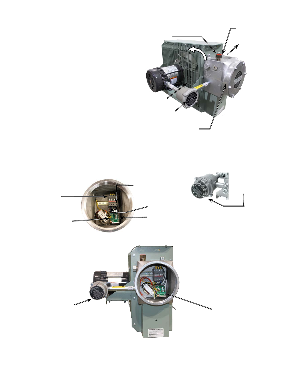
FIGURE 8
FIGURE 7A
FIGURE 6
Optional factory
installed built-in
room thermostat.
3. The internal grounding terminal in the control enclosure shall be
used as the equipment grounding means. An external bonding
terminal (see Figure 6) is provided for a supplementary bonding
connection where local authorities permit or require such a
connection.
FIGURE 7B
F I N A L I N S P E C T I O N
1. Before application of electrical power:
a. Check that all connections are secured and comply with the
applicable wiring diagram (see Figure 9) and code requirements,
b. Confirm that the power supply is compatible with the data plate
rating of the heater,
c. Remove any foreign objects from the heater,
d. Install all covers and verify that all enclosures are well secured, and
e. Ensure that the fan rotates freely. See Figure 6 for proper direction
of fan rotation.
Remote Room
Thermostat
if applicable
Terminals marked
“T’STAT”
Air
intake
Fan
rotation
Rear View of Heater
M25 or M32
opening for
field wiring
Motor
junction box
Control enclosure
and cover
Air exits through
louvers.
Connect supply conductors
to this side of contactor.
For a 1-phase heater, use
these contactor terminals
Contactor load
side terminals,
this side for
factory wiring
only.
Active and spare
fuses (see parts list)
Printed circuit board’s
terminal block
Control Enclosure & Field Wiring
External
Bonding