Warning, Electrical – CCI Thermal Technologies FE2 - Explosion-Proof Electric Air Unit Heater User Manual
Page 6
6
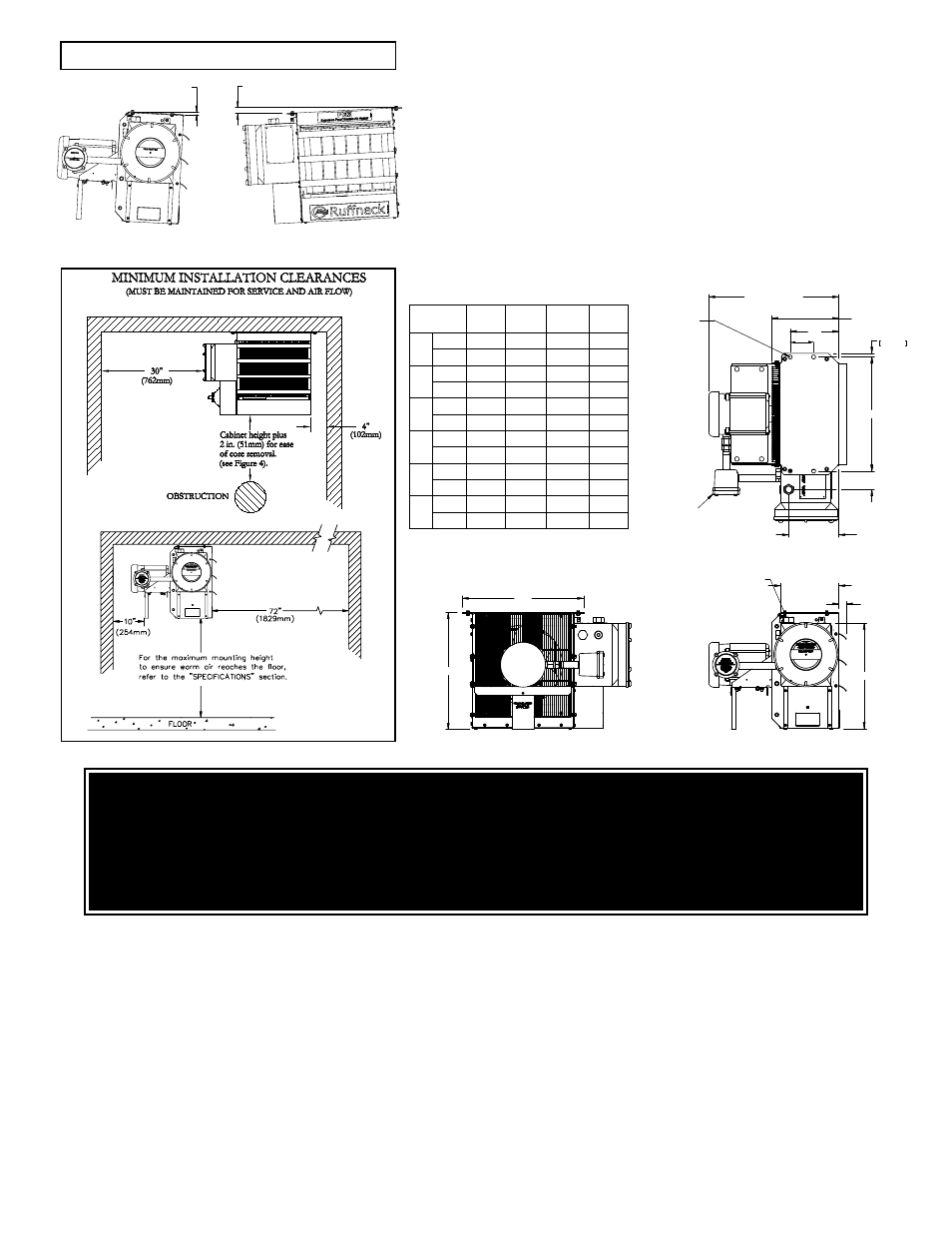
MAXIMUM TILT ANGLES
(EITHER DIRECTION)
WARNING
Disconnect heater from power supply at fuse box before opening enclosures or servicing heater.
Lock the switch in the "OFF" (open) position and/or tag the switch to prevent unexpected power application.
Verify that power has been disconnected at fuse box or main panel. Lock the switch in the "OFF" (open) position
and/or tag the switch to prevent unexpected power application.
Installation and wiring of the heater must adhere to all application codes.
G E N E R A L
1. Use only copper conductors and approved explosion-
proof wiring methods during installation. Refer to the “Technical
Data” table and heater data plate for conductor rating.
2. External overcurrent protection is required. Refer to the
“Technical Data” table and heater data plate for voltage,
frequency amperage, and phase. Supply voltage is to be within
10% of the data plate voltage.
3. The heater must be installed by qualified personnel in strict
compliance with electrical codes.
4. All heaters come factory prewired and ready for direct
connection to the power supply leads.
5. The heater must be individually fused, preferably with Class J
time-delay fuses for maximum safety. Unless stated otherwise in
your local code, fuse size shall be 125% of line current or next
size larger.
F I E L D W I R I N G
1. The supply conductors, ground conductor, and room thermostat
conductors all pass through the M32 or M25 opening
(see Figure 6) and are to be wired into the control enclosure
(see Figure 7A).
2. Heater may be supplied with a factory installed built-in room
thermostat (see Figure 8). On heaters not supplied with this
option, it is recommended that a remote room thermostat be
used. Connect the remote room thermostat conductors to the
printed circuit board terminal block marked “TSTAT”.
Any thermostat used with this heater must:
a. be of an explosion-proof type,
b. be rated 125V minimum,
c. have a minimum 2 amp capacity, and
d. open on temperature rise.
FIGURE 3
FIGURE 4
M O U N T I N G
1. The heater must be permanently mounted in a level,
upright position for operation. See Figures 3, 4, and 5
for maximum tilt angles, installation clearances, and
physical dimensions. For ease of installation, a variety
of mounting kits are available from the factory.
2. The mounting structure must be strong enough to:
a. support the heater’s weight, refer to the
“Specifications” section,
b. provide sufficient stiffness to prevent excessive
vibration, and
c. withstand harsh situations such as
transportable installations.
FIGURE 5
ELECTRICAL
10 13/16" u3/16
[274 u5mm]
A
22 5/8" [575mm]
MAX.
9/16"
15mm
B
3" u1/4"
[76 u6mm]
8 1/16" u1/4"
[206 u6mm]
Ш5/8" [Ш15.9mm]
MOUNTING HOLE
(4 PLCS)
MOTOR JUNCTION BOX
& OPTIONAL BUILT-IN
THERMOSTAT
M25 OR M32 (FOR REMOTE
ROOM THERMOSTAT,
IF APPLICABLE)
9 5/16" u1/4"
237 u6mm]
1 1/2"
[38mm MAX.]
E
D
F
3 3/4”
0.5"
(12.7mm)
1"
(25.4mm)
3. Do not install conduit below heater (see Figure 4 ).
DIM
2.5 - 10
kW
12.5 - 20
kW
20.9 - 35
kW
DIM.
TOL ±
A
mm
198
195
196
3
in
7.75
7.69
7.71
0.13
B
mm
462
566
667
3
in
18.19
22.31
26.25
0.13
C
mm
686
787
889
4
in
27
31
35
0.19
D
mm
470
572
674
3
in
18.50
22.50
26.50
0.13
E
mm
494
596
697
10
in
19.44
23.44
27.44
0.38
F
mm
444
495
554
8
in
17.50
19.50
21.81
0.31
DIMENSIONAL TOLERANCES
± 3 mm (0.125")
UNLESS OTHERWISE SPECIFIED.