Technical data, Troubleshooting, Controller – Viking Pump TSM630.4: K-QS 124E Controller User Manual
Page 9: Relay
SECTION TSM 630.4
ISSUE
D
PAGE 9 OF 10
TECHNICAL DATA -
Controller
TECHNICAL DATA -
Relay
TROUbLESHOOTING
Weight
6.6 oz. (186 g)
Supply Voltage
1x220-240 (±10%)
Frequency
50 or 60 Hz
Power Consumption
Max 10 VA
Fuses
Use Max 15 A
Terminal Wire Size
Use 18 to 12 AWG
Terminal Tightening Torque
7 lb-in (0.8 Nm)
Max Temperature Error @ Ambient ± 3.15°F (1.75 °C)
Sampling Rates for Input & Output 10 Hz
Heater Relay (L2,k2)
NO-ARC 15A, Form A
Ready Light Relay (L1,k1)
Mechanical Relay 5A, Form C
Operating Temperature
0-149°F (-18-65°C)
Storage Temperature
-40-185°F (-40-85°C)
Allowable Humidity
0 to 90%; non-condensing
Protection Class
NEMA 4X/IP66 if installed correctly (see
assembly step 4)
Pollution Degree
Pollution Degree 2
back-up battery Information
• Allows for data retention upon power failure
• Battery Type: lithium (recycle properly)
• Typical Battery Life: three cumulative years
of unpowered life at 77°F (25°C)
Agency Approvals
• UL® Listed to UL® 61010-1 File E185611
• UL® Reviewed to CSA C22.2 No.61010-1-04
• UL® 50 Type 4X
• FM Class 3545 File 3029084 temperature
limit switches
• CE, RoHS, and W.E.E.E. compliant
• Suitable for use in Class 1, Div 2, Groups A,
B, C and D or non-hazardous locations only.
Temperature Code T4A
• UL® Listed to ANSI/ISA 12.12.01-2007 File
E184390
• CSA approved; CSA C22. No. 24 File
158031 Class 4813-02
• UL® reviewed to Standard No. CSA C22.2
No. 213-M1987
Weight
1.6 lbs (0.7 kg)
Supply
Voltage
85V minimum -
660V maximum
Frequency
50 or 60 Hz
Power
Consumption 1.2 watts per amp switched
Storage
Temperature -40 - +185°F (-40 - +85°C)
Allowable
Humidity
0 to 90%; non-condensing
Protection
Class
IP20
Pollution
Degree
Pollution Degree 2
Classification Power Control; Installation III
Agency
Approvals
• UL® 508 Listed and C-UL®,
File E73741
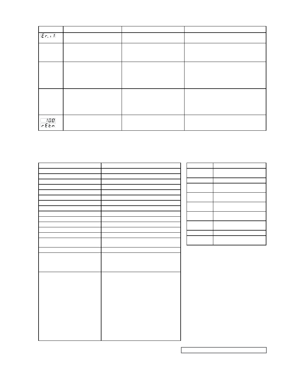
Error Code
Description
Possible Causes
Corrective Action
Error Input
Sensor does not provide a valid signal
to controller
1. Thermocouple improperly wired or open 1. Correct wiring or replace thermocouple
No heat
action
Output does not activate load
1. Output is incorrectly wired
2. Load, power, or fuse is open
3. Set point is incorrect
4. Heat cartridge is burnt out*
1. Correct output wiring
2. Correct fault in system
3. Adjust set point to correct temperature
4. Replace heat cartridge
No display
No display indication or LED illumination 1. Power to controller is off
2. Fuse open
3. Breaker tripped
4. Safety interlock switch open
5. Wiring error
6. Incorrect voltage to controller
1. Turn on power
2. Replace fuse between power source and controller
3. Reset breaker
4. Close interlock switch
5. Correct wiring issue
6. Check voltage requirements and apply correct voltage
Temperature
runaway
Process value continues to increase
past set point
1. Thermocouple reverse wired
2. Controller output wired incorrectly
3. Short in heater
4. Power controller connection to controller
defective
5. Controller ouput defective
1. Correct thermocouple wiring (red wire negative)
2. Verify and correct wiring
3. Replace heater
4. Replace or repair power controller
5. Replace or repair controller
Device Error
Controller displays internal malfunction
message at power up.
1. Controller is defective
1. Replace or repair controller
* Use an ohmmeter or multimeter to determine the resistance across the
heat cartridge. A burnt out heater will have a reading of infinity (∞) ohms.
The customer supplied fuse between the heat cartridges and controller
will typically blow when one of the heat cartridges fails