Installation, Danger, Controller – Viking Pump TSM630.4: K-QS 124E Controller User Manual
Page 4
SECTION TSM 630.4
ISSUE
D
PAGE 4 OF 10
DANGER !
All electrical power to the controller and
controlled circuits must be disconnected
before removing the controller from the front
panel or disconnecting other wiring.
Failure to follow these instructions may cause
an electrical shock and/or sparks that could
cause an explosion in class 1 div. 2 hazardous
locations.
Removing The Mounted Controller
From Its Case
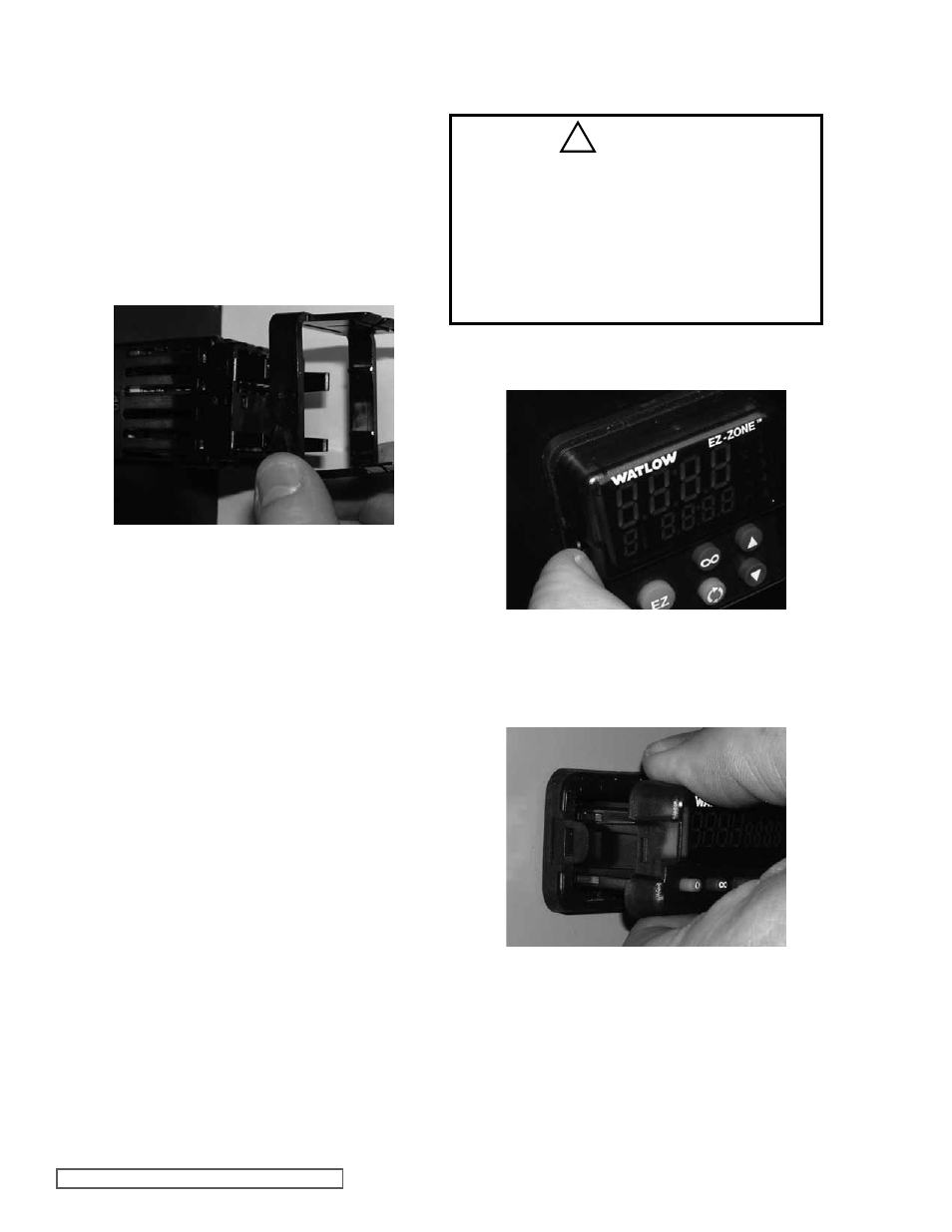
Returning the Controller to its Case
1. From the face side of the controller, pull out the tabs on
each side until you hear it click.
1. Ensure that the orientation of the controller is correct and
slide it back into the housing. The controller is keyed so
it should slide easily back in to the case.
Do not force it.
Verify orientation again if it will not slide back into the case.
2. Using your thumbs push on either side of the controller
until both latches click.
2. Once the sides are released grab the unit above and
below the face with two hands and pull the unit out.
Pull out the tab on each
side until you hear it click.
Grab the unit above and below
the face and pull forward.
INSTALLATION
Controller
Assembly
1. Make the panel cutout using the mounting template
dimensions shown in
Figure 1.
2. Insert the case assembly into the panel cutout.
3. While pressing the case assembly firmly against the panel,
slide the mounting collar over the back of the controller.
If the installation does not require a NEMA 4X (UL50, IP66)
seal, simply slide together until the gasket is compressed.
4. For a NEMA 4X (UL50, IP66) seal, alternately place and
push the blade of a screwdriver against each of the four
corners of the mounting collar assembly. Apply pressure
to the face of the controller while pushing with the
screwdriver.
Don’t be afraid to apply enough pressure to properly install
the controller. The seal system is compressed more by
mating the mounting collar tighter to the front panel. If
you can move the case assembly back and forth in the
cutout, you do not have a proper seal.
The tabs on each side of the mounting collar have teeth
that latch into the ridges on the sides of the controller.
Each tooth is staggered at a different depth from the front
so that only one of the tabs on each side is locked onto
the ridge at a time.
Note: There is a graduated measurement difference
between the upper and lower half of the display to
the panel. In order to meet the seal requirements
mentioned above, ensure that the distance from the
front of the top half of the display to the panel is
0.630 in. (16 mm) or less, and the distance from the
front of the bottom half and the panel is 0.525 in.
(13.3 mm) or less.
Slide the mounting collar over
the back of the controller.
!