Wiring, Danger – Viking Pump TSM630.4: K-QS 124E Controller User Manual
Page 6
PID
15A
L1
K1
S1
R1
K2
L2
99
98
15A
NOT READY LIGHT
J1
READY LIGHT
SECTION TSM 630.4
ISSUE
D
PAGE 6 OF 10
WIRING
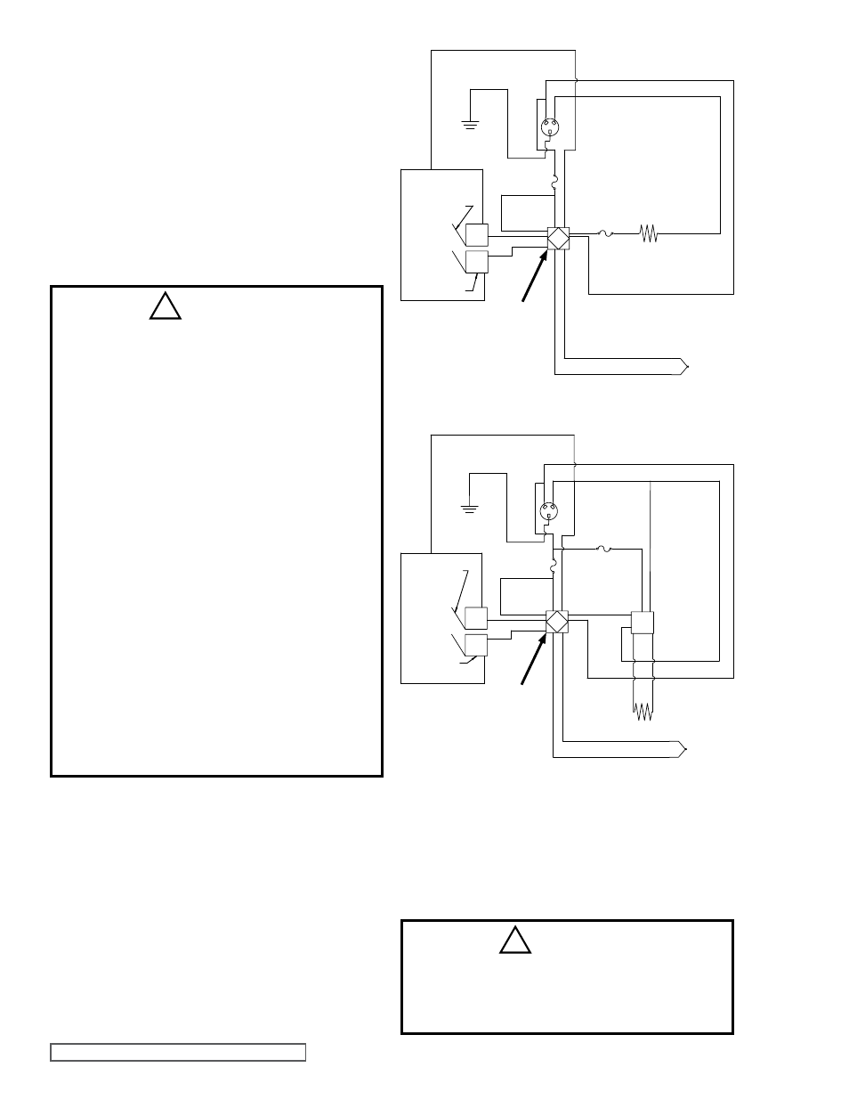
For H-QS pumps, the wiring diagram in
Figure 2 shows how
the controller is wired to the power source, cartridge heaters,
ready light, and thermocouple.
Figure 4 shows the layout of
the terminals on the controller. The terminal descriptions of
the controller are given in
Table 1.
For N size pumps, the wiring diagram in
Figure 3 shows how
the controller is wired to the power source, cartridge heaters,
relay, ready light, and thermocouple.
Figure 4 shows
the layout of the terminals on the controller, and
Figure 5
shows the layout of the terminals on the relay. The terminal
descriptions of the controller are given in
Table 1, and the
relay terminal descriptions are given in
Table 2.
DANGER !
• Always disconnect, lockout, and tag out
supply circuits prior to installing.
• Use National Electric (NEC) or other country-
specific standard wiring and safety practices
when wiring and connecting this controller
to a power source and to electrical sensors
or peripheral devices. Failure to do so may
result in damage to equipment and property,
and/or injury or death.
• The installation must comply with standard
and local regulations.
• All wiring should be done by a licensed
electrician to meet local codes.
• Study this manual thoroughly before installing
and using the controller.
• Pay special attention to this section and the
parts marked “WARNING!” or “DANGER”.
• Should questions or uncertainties arise, please
contact your authorized Viking distributor.
• Proper selection and installation of the
thermocouple wiring and cartridge heater
wiring is the responsibility of the end user.
Refer to the temperature controller manual for
instructions.
FIGURE 2 - WIRING DIAGRAM FOR H-QS SIZE PUMPS
FIGURE 3 - WIRING DIAGRAM FOR N SIZE PUMP ONLY
Power Source
Fuse
Fuse
Heat
Cartridges
Controller
Thermocouple
*
Thermocouple
*
!
PID
SSR
40A
L1
K1
S1
R1
K2
L2
99
98
15A
NOT READY LIGHT
J1
READY LIGHT
7
8
3
2
5
6
Power Source
Fuse
Relay
Fuse
Heat
Cartridges
Controller
DANGER !
Do not put a fuse or switch on the neutral line
coming into terminal 3. Failure to follow this
guideline could result in personal injury or
death.
!
NOTES:
*
Thermocouples are polarity sensitive. The negative lead
(usually red) must be connected to S1.
The extension wire for thermocouples must be of the same
alloy as the thermocouple.