Viking Pump TSM630.2: LS-QS Universal Seal User Manual
Page 9
SECTION TSM 630.2
ISSUE
I
PAGE 9 OF 12
PUMP
SIZE
MODEL
STANDARD
END
CLEARANCE
(Inch)
TURN BRG.
HOUSING
C.C.W.
LENGTH ON
O.D.
(Inch)
ADDITIONAL
LENGTH ON
O.D. BRG.
HOUSING FOR
.001” END CL.
(Inch)
LS
124A
4124A
126A
4126A
123A
4123A
.005
1.25
224A
224AH
4224A
4224AH
226A
4226A
223A
4223A
124E
124EH
.010
2.50
.25
127A
4127A
.010
2.50
227A
4227A
.20
5.00
Q
QS
124A
4124A
126A
4126A
123A
4123A
.010
3.10
224A
4224A
226A
4226A
223A
4223A
124E
.015
4.65
.31
127A
4127A
.010
3.10
227A
4227A
.020
6.20
TABLE 1
When installing carbon graphite bushings, extreme care must
be taken to prevent breaking. Carbon graphite is a brittle
material and easily cracked. If cracked, the bushing will
quickly disintegrate. Using a lubricant and adding a chamfer
on the bushing and the mating part will help in installation.
The additional precautions listed below must be followed for
proper installation.
1. A press must be used for installation.
2. Be certain bushing is started straight.
3. Do not stop pressing operation until bushing is in proper
position. Starting and stopping will result in a cracked
bushing.
4. Check bushing for cracks after installation.
INSTALLATION OF CARBON
GRAPHITE BUSHINGS
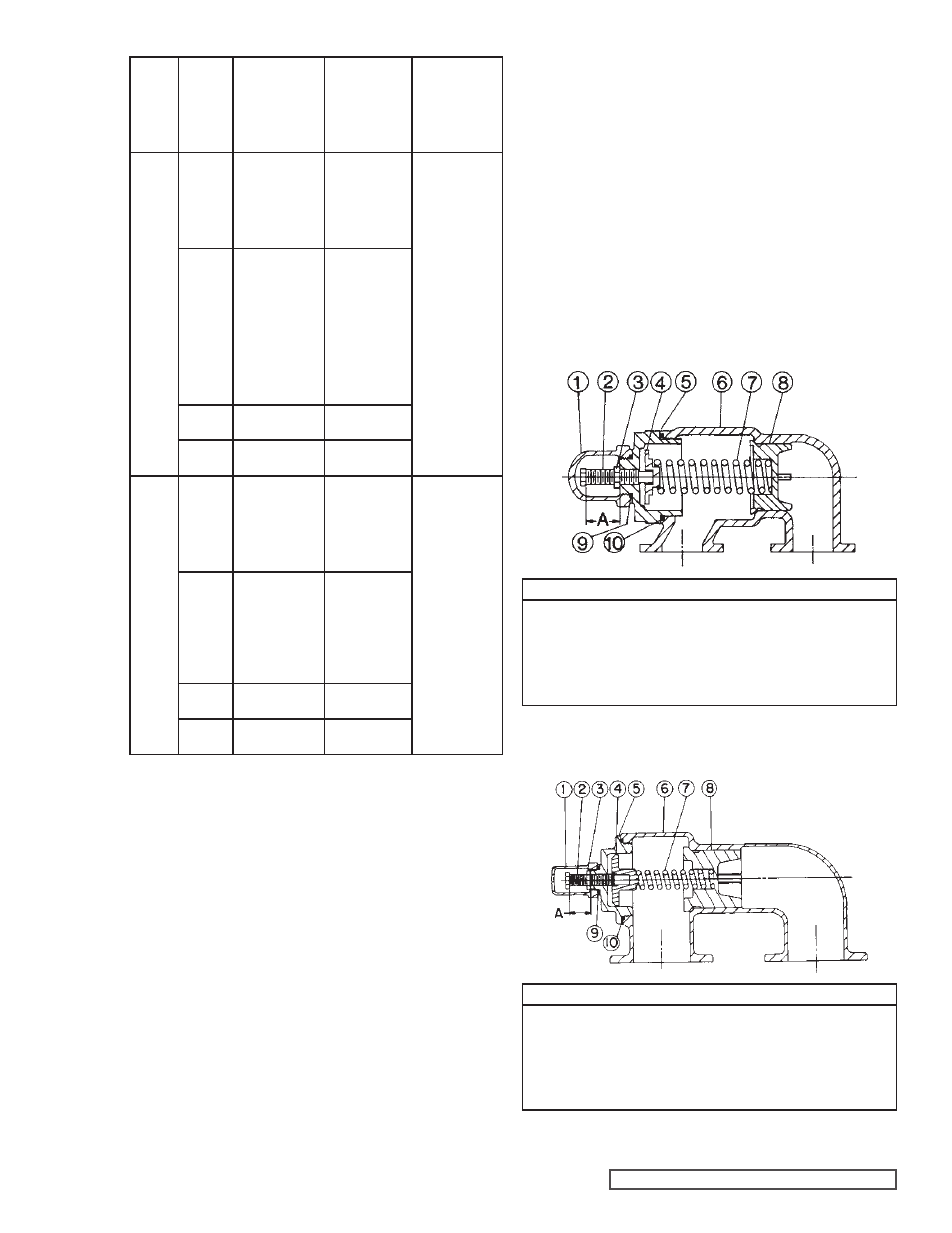
PRESSURE RELIEF VALVE
INSTRUCTIONS
VALVE - LIST OF PARTS
1. Valve Cap
6. Valve Body
2. Adjusting Screw
7. Valve Spring
3. Lock Nut
8. Poppet
4. Spring Guide
9. Cap Gasket
5. Bonnet
10. Bonnet Gasket
FIGURE 12
SIZE LS
Carbon graphite bushings with extra interference fits are
frequently furnished for high temperature operation. These
bushings must be installed by a shrink fit.
1. Heat bracket for idler to 750ºF.
2. Install cool bushing with a press.
3. If facilities are not available to reach 750ºF. temperature,
it is possible to install with 450ºF. temperature; however
the lower the temperature the greater the possibility of
cracking the bushing.
4. Consult factory with specific questions on high
temperature applications.
Refer to Engineering
Service Bulletin ESB-3.
VALVE - LIST OF PARTS
1. Valve Cap
6. Valve Body
2. Adjusting Screw
7. Valve Spring
3. Lock Nut
8. Poppet
4. Spring Guide
9. Cap Gasket
5. Bonnet
10. Bonnet Gasket
FIGURE 13
SIZES Q AND QS