Assembly – Viking Pump TSM630.2: LS-QS Universal Seal User Manual
Page 5
SECTION TSM 630.2
ISSUE
I
PAGE 5 OF 12
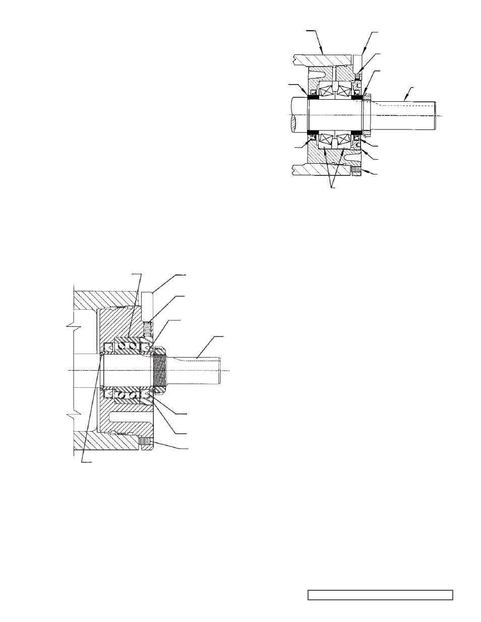
FIGURE 5
LS BEARING HOUSING ASSEMBLY
FIGURE 6
Q-QS BEARING HOUSING ASSEMBLY
7. Carefully remove rotor and shaft to avoid damaging
bracket bushing.
8. Loosen two radial setscrews in flange of bearing housing
and with a spanner wrench remove the outer end cap
with closure and outer bearing spacer collar.
9. Remove the double row ball bearing, (2 tapered roller
bearings on “Q” and “QS” sizes), closure and inner
bearing spacer collar from the bearing housing.
10. Clean all parts thoroughly and examine for wear and
damage. Check lip seals, bearings, bushings, and idler
pin and replace if necessary. Check all other parts for
nicks, burrs, excessive wear and replace if necessary.
Wash bearings in clean solvent. Blow out bearings with
compressed air. Do not allow bearings to spin; turn
them slowly by hand. Spinning bearings will damage
bearing components. Make sure bearings are clean,
then lubricate with light oil and check for roughness.
Roughness can be determined by turning outer race by
hand.
CAUTION: Do not intermix inner and outer races of tapered
roller bearing (“Q” and “QS sizes).
11. Casing can be checked for wear or damage while
mounted on bracket.
12. Inspect bracket bushing for wear and remove if damaged
or worn.
1. Install bracket bushing. If bracket bushing has a
lubrication groove, install bushing with groove at 6.00
o’clock position in bracket. If carbon graphite,
Refer to
Installation of Carbon Graphite Bushings, page 9.
2. Coat shaft of rotor shaft assembly with light oil. Start
end of shaft in bracket bushing turning from right to left,
slowly pushing rotor in casing.
3. Coat idler pin with light oil and place idler and bushing
on idler pin in head. If replacing with carbon graphite
bushing,
Refer to Installation of Carbon Graphite
Bushings, page 9.
4. Using a .010 to .015 inch thick head gasket, install head
and idler assembly on pump. Pump head and casing
should have been marked before disassembly to insure
proper reassembly. If not, be sure idler pin, which is
offset in pump head, is positioned toward the equal
distance between port connections to allow for proper
flow of liquid through pump.
Refer to Figure 5 and 6 for bearing housing assembly.
5. Install the lipseal in the bearing housing (See the
appropriate figure for lip orientation).
6. “LS” Pumps: Pack the ball bearing with grease and
push or press the bearing into the bearing housing.
Refer to Figure 5.
“Q” and “QS” Pumps: Pack tapered roller bearings
with grease and press or push bearings into housing with
large end of inner races together. It is possible to install
bearings incorrectly. For proper assembly see Figure 6.
7. Install the lipseal in the end cap (see appropriate figure
for lip orientation). Thread the end cap into the bearing
housing along with outer bearing spacer collar and
tighten against the bearing.
ASSEMBLY
TAPERED ROLLER BEARING
BALL BEARING
BEARING HOUSING
SETSCREW
SPACER COLLAR
SHAFT
LIPSEAL
END CAP
HALF ROUND RINGS
BRACKET
SETSCREW
BEARING HOUSING
SPACER COLLAR
SHAFT
LIPSEAL
END CAP
LIPSEAL
SETSCREW
SPACER
COLLAR
SETSCREW