Thrust bearing adjustment – Viking Pump TSM630.2: LS-QS Universal Seal User Manual
Page 8
SECTION TSM 630.2
ISSUE
I
PAGE 8 OF 12
For complete pump assembly instructions,
see Assembly,
page 5.
1. Clean rotor shaft and seal housing bore. Make sure they
are free of dirt, grit and scratches. Gently radius leading
edge of shaft diameter over which seal is to be placed.
NOTE: Never touch mechanical seal faces with anything
except clean hands or clean cloth. Minute particles can
scratch the seal faces and cause leakage.
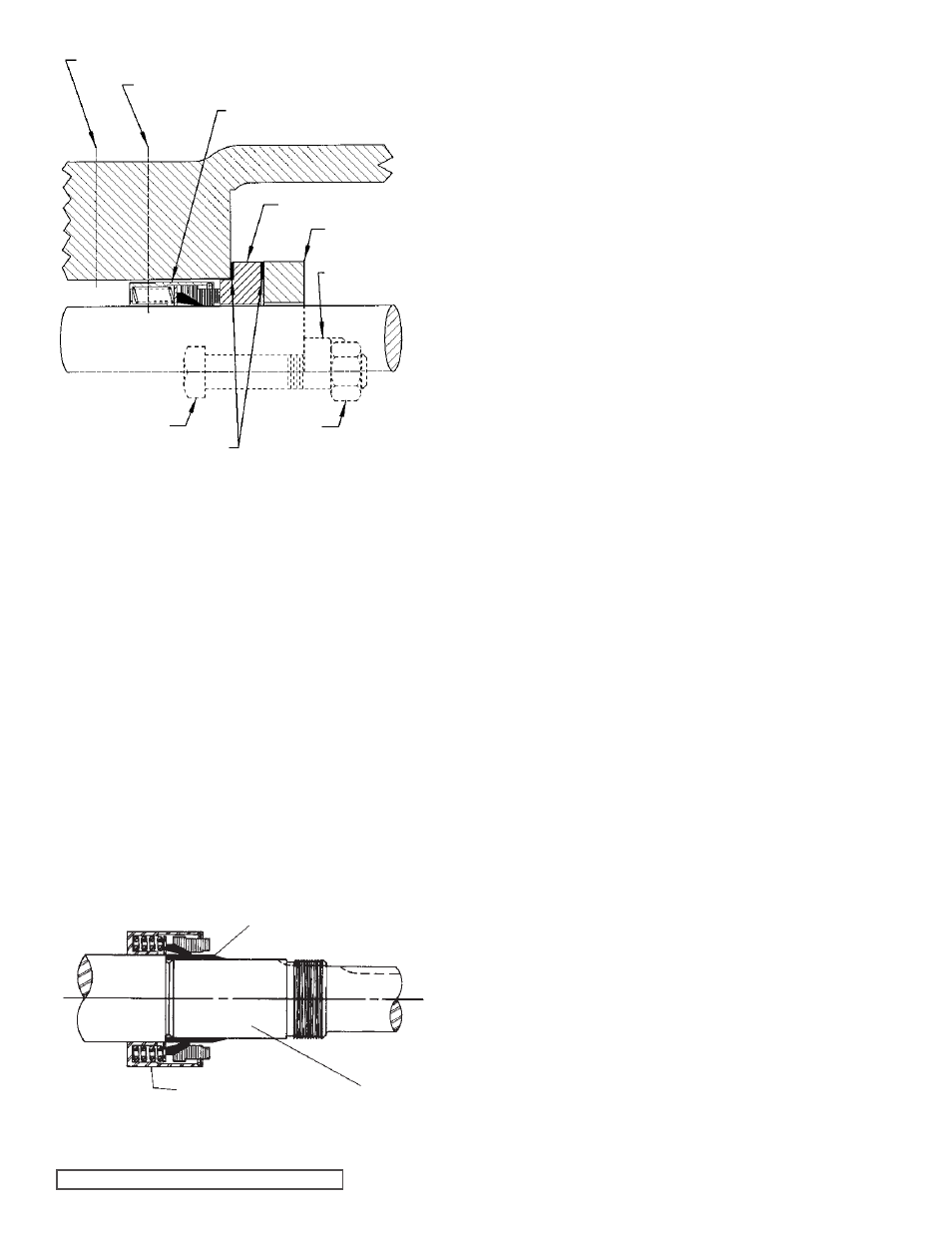
2. Place tapered installation sleeve on the shaft (See
Figure 11). Q, QS sizes only.
3. Coat outside of tapered installation sleeve and inside of
rotary member of the seal with a generous quantity of
light oil. Grease is not recommended.
4. Start rotary member on shaft (including seat collar and
screws on bellows seal) and ease over tapered sleeve
(See Figure 11).
ELASTOMERIC BELLOWS AND
PTFE WEDGE TYPE - Q,QS SIZES
FIGURE 11
FIGURE 10
PTFE WEDGE SEAL
NOTE: Some PTFE wedge seals are equipped with
holding clips, which compress the seal springs. Remove
holding clips to release springs after seal is installed on
shaft.
5. Move rotary member so set screws are directly below
seal access holes on side of bracket
(See Figure 9,
page 7 and Figure 10). Tighten all setscrews securely
to shaft.
NOTE: Be sure that the rotor and shaft are positioned
against the head before tightening set screws.
6. FOR “O-RING” GASKET TYPE MECHANICAL SEAL
SEAT (BELLOWS SEAL): Lubricate outer diameter of
O-ring seal gasket with oil. Flush sealing faces of both
rotary member and seal seat with oil and press seal seat
in to bore until back, unlapped face, is flush with bore.
Install seal holder, seal plate, capscrews, and nuts and
tighten securely.
FOR “CLAMPED-IN” TYPE MECHANICAL SEAL
SEAT (WEDGE SEAT): Flush sealing faces of both
rotary member and seal seat with oil and install seal
seat and seat gasket over end of shaft against machined
bracket face. Install other seal gasket, seal holder, seal
plate, capscrews and nuts and fasten securely.
7. Remove tapered installation sleeve.
8. Connect circulation line or vent stuffing box for seals
without flush line until liquid is present on start up.
NOTE: For maximum seal life, circulation line should
be used.
Refer to Assembly, page 5 to complete assembly.
1. Loosen the two set screws in the outer face of the
bearing housing and turn this thrust bearing assembly
clockwise until it can no longer be turned by hand. Back
off counter-clockwise until the rotor shaft can be turned
by hand with a slight noticeable drag.
2. For standard end clearance, back off the thrust bearing
assembly the required length measured on the outside
diameter of the bearing housing.
See Table 1, page 9.
3. Tighten the two self-locking type “Allen” set screws, in
the outboard face of the bearing housing, with equal
force against the bracket. Your pump is now set with
standard end clearances and locked.
NOTE: Be sure the shaft can rotate freely. If not, back off
additional length on outside diameter and check again.
4. High viscosity liquids required additional end clearances.
The amount of extra end clearance depends on
the viscosity of the liquid pumped. For specific
recommendations, consult the factory. Table 1 shows
the additional bearing housing adjustment required for
.001” increase in end clearance.
THRUST BEARING ADJUSTMENT
SHAFT
MECHANICAL SEAL
ROTARY MEMBER
FLUSH CONNECTION
SEAL ACCESS HOLE
MECHANICAL SEAL
(ROTARY MEMBER)
SEAL SEAT
SEAL HOLDER
SEAL PLATE
NUT
CAPSCREW
SEAL GASKET
TAPERED INSTALLATION SLEEVE