Viking Pump TSM630.2: LS-QS Universal Seal User Manual
Page 11
SECTION TSM 630.2
ISSUE
I
PAGE 11 OF 12
NOTE:
1. Heat cartridges, temperature probes, and controllers
must be wired by a licensed electrician to meet local
codes.
2. Heat cartridges require 240VAC, 1 Phase, 60 Hz or
220VAC, 1 Phase, 50 Hz power supply.
3. Heat cartridges are UL, CSA, & CE marked, RoHs
compliant.
4. Heat cartridges and cables are water resistant but not
water proof. They need to be installed in a protected
area.
5. To make sure that the liquid within the pump is melted
and to avoid damage to the pump, do not start the pump
until the set point temperature has been reached.
6. Several factors such as the size of pump, the set point
temperature, and the insulation will affect the amount
of time it will take for the pump to reach the set point
temperature. Typically it will take 3-4 hours for the pump
to reach its set point temperature.
7. Do not use heat cartridges with different watt densities
from those supplied by Viking. Changing watt densities
may result in localized over or under heating.
8. The thermocouple or temperature probe must be
installed in the bracket location shown in Figure 13
below. Any other location may result in localized over or
under heating.
9. Please see TSM 630.4 for technical information on the
Viking supplied controller for the heat cartridges.
10. The wires for the heat cartridges can be joined together
in a junction box, and a single wire from the junction box
can be connected to the controller.
11. WARNING Heat cartridges will be hot. Do not touch
pump or heat cartridges until they have been allowed to
cool.
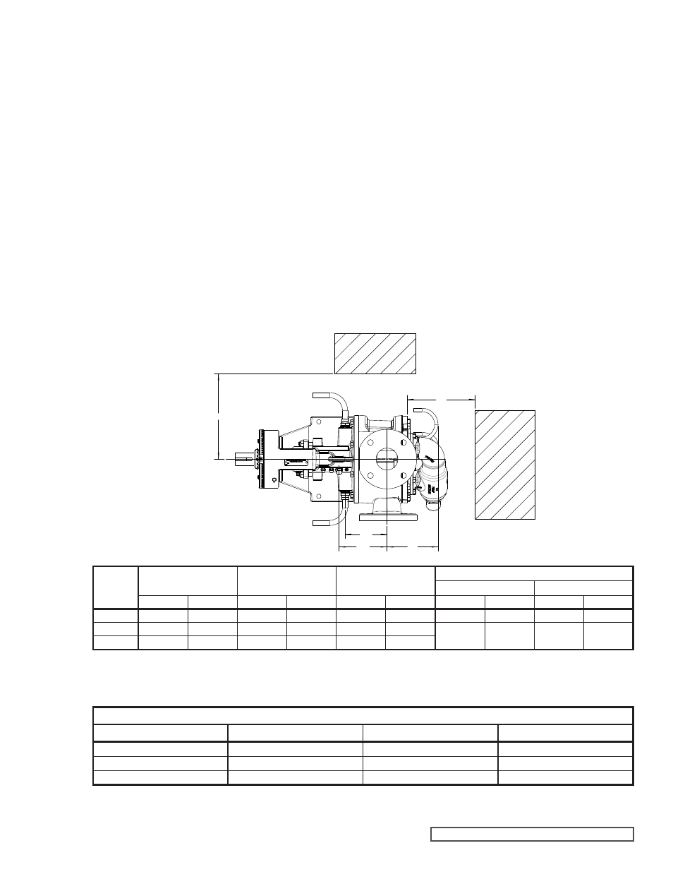
FIGURE 13 - HEAT CARTRIDGE AND THERMOCOUPLE LOCATIONS
TABLE 2 - NUMBER OF HEAT CARTRIDGES IN EACH PUMP MODEL
* The thermocouple location for the LS size is
located on the opposite side of the bracket as
shown in the drawing.
Dimensions - LS through QS Sizes – Electrically Heated – Non Jacketed
(Top View)
Wattage by Pump Size
Pump Size
Number of Heaters in Head
Number of Heaters in Bracket
Total Wattage
LS
2
2
1250
Q
3
2
2200
QS
3
2
2200
Model
Bracket Heater to Port
Center Line (DD)
Temp Probe to Port
Center Line (CC)
Head Heater to Port
Center Line (EE)
Required to Remove Heater
(AA)
(BB)
Inch
mm
Inch
mm
Inch
mm
Inch
mm
Inch
mm
LS124E
6.09
154.69
6.25
158.75
6.44
163.58
7.00
177.80
6.50
165.10
Q124E
5.83
148.08
7.33
186.18
8.25
209.55
9.25
234.95
7.75
196.85
QS124E
6.33
160.78
7.83
198.88
9.25
234.95
AA
BB
EE
DD
CC