Assembly, C” reducer assembly - see fig. 9 – Viking Pump TSM610: Offset Gear Reducers User Manual
Page 6
ITEM
NAME OF PART
ITEM
NAME OF PART
ITEM
NAME OF PART
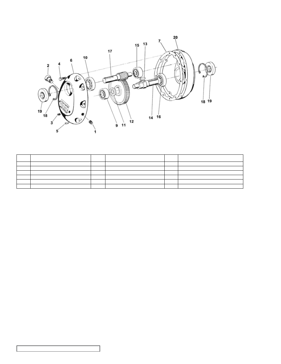
1
Drain Plug
7
Gasket
14
Gear Shaft
2
Breather
9
Ball Bearing (Double Row)
15
Ball Bearing (Double Row)
3
Pipe Plug (Set-2)
10
Ball Bearing (Single Row)
16
Ball Bearing (Single Row)
4
Capscrew (Set-2)
11
Spacer
17
Pinion and Shaft
5
Dowel Pin Locating (Set-2)
12
Gear
18
Snap Ring (Set-2)
6
Gear Case Cover
13
Key
19
Lip Seal (Set-2)
SECTION TSM
610
ISSUE
G
PAGE 6 OF 8
1. Install the ball bearing on the pinion shaft; the double row
bearing on the small diameter end, and the single row
bearing on the large diameter end. Be sure the bearings
are seated firmly against the shoulders on the shaft.
NOTE: The pinion and shaft for “C” reducer (7.95 to 1
ratio) is furnished with a snap ring. This snap ring must
be installed in the groove on the shaft prior to bearing
assembly. The bearing should be seated against the snap
ring.
2. Install the square key in the gear shaft and press the gear
into place. Be sure the gear seats against the shoulder on
the shaft.
3. Place the spacer on the gear shaft with bevelled edge
toward the gear. Install the bearing over gear shaft and
seat firmly against the spacer. Install a second bearing
on large end of the gear shaft and seat the bearing firmly
against the shaft shoulder.
4. If the lip seals have been removed during disassembly
place gear case and cover, gaskets face down, on surface
which will not mar the face. Be sure the snap rings are in
the face and cover. Put gasket sealer on the O.D. of lip
seals. Drive new lip seals with lip toward the inside of the
reducer, in place against the snap rings. Use a wood block
covering entire lip seal and drive evenly. Apply lubricant to
lip seal surfaces.
5. Block the gear case, open side up, to provide at least
3¾” clearance between case and assembly bench.
6. Make certain the pinion and gear shaft keyways are free
of burrs and sharp edges to prevent damaging the lip seal
sealing surfaces. Take the pinion and gear assemblies,
mesh the gear teeth, and insert simultaneously into the
gear case half. Rotate the gear shaft slightly as it is
pushed through the lip seal. Tap the end of the pinion
shaft and gear shaft with hardwood block to seat the
bearings in the counter bores.
7. Place the gasket on gear case. If the gasket is damaged,
discard it and use a new gasket.
8. Align the gear case cover with the ends of the pinion
and gear shafts, and carefully push the cover into place.
Rotate the pinion shaft during assembly. Tap the cover
with a hardwood block to seat the bearings in cover.
9. Install the seven capscrews and nuts and tighten
securely, alternating around the gear case to prevent
distortion.
10. Install the drain plug. Be sure the reducer is filled with
proper lubricant. See “Lubrication” instructions, page 2.
ASSEMBLY
“C” Reducer Assembly - See Fig. 9
FIGURE 9
“C” SIzE hELICAL GEAR REDUCER - ExPLODED VIEW