Assembly, A” reducer assembly - see fig.7 – Viking Pump TSM610: Offset Gear Reducers User Manual
Page 4
1. Install ball bearings on the pinion shaft. Be sure the
single row bearings are seated firmly against the shoulders
on the pinion shaft.
2. Install the square key in the gear shaft and press the
gear into place.
3. Be sure the gear is centered on the shaft. Install the ball
bearings on each side of the gear. Be sure the bearings
are seated firmly against the gear and the shaft is still
centered.
4. If the lip seal has been removed during disassembly,
place the gear case halves, gasket faces down, on a
surface which will not mar the face. Put gasket sealer on
O.D. of lip seals. Drive new lip seals into the gear case
halves (lip towards inside of reducer) with a wood block
covering entire lip seal. Drive evenly until the lip seals
are flush with the outer face of the gear case halves.
5. If steel covers have been removed during disassembly,
install one cover in the bore of the gear case half opposite
the pinion shaft extension. This cover should be flush
with outer edge of case. Install a second cover in the bore
of the gear case half, opposite the gear shaft extension
.090 below the surface of the gear case. NOTE: Coat the
side of the covers with sealer and drive the cover from
the inside of case towards outside of case.
6. Apply lubricant to the lip seal sealing surfaces.
7. Block the gear case, open side up, to provide at least 2”
clearance between the case and the assembly bench.
8. Make certain the pinion and gear shaft keyways are
free of burrs and sharp edges to prevent damaging the
sealing surfaces in the lip seals.
9. Take the pinion and gear assemblies, mesh the gear
teeth and insert simultaneously into the gear case half.
Rotate the gear shaft slightly as it is pushed through the
lip seal. Tap the end of pinion shaft and gear shaft with a
hard wood block to seat the bearings in the counterbores.
10. Place gasket on the gear case. If the gasket is damaged,
discard it and use a new gasket.
11. Align the gear case half with ends of the pinion and
gear shafts, and carefully pass the other half into place.
Rotate the pinion shaft during assembly. Tap the gear
case with a hard wood block to seat the bearings.
12. Install the six capscrews and nuts and tighten securely,
alternating around gear case to prevent distortion.
13. Install drain plug. Be sure the proper amount and type of
lubricant is added. See “Lubrication” instructions, page 2.
SECTION TSM
610
ISSUE
G
PAGE 4 OF 8
ASSEMBLY
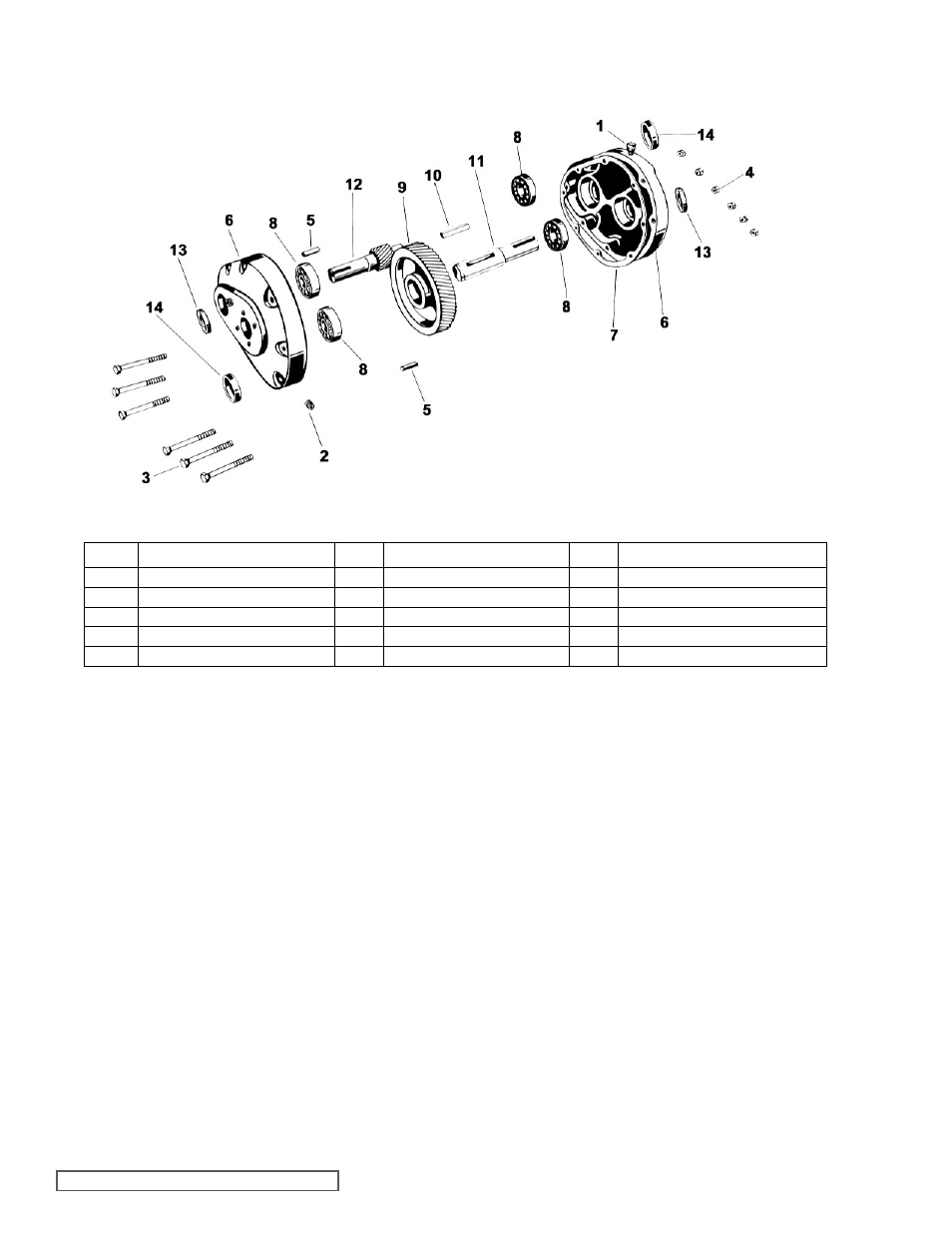
“A” Reducer Assembly - See Fig.7
ITEM
NAME OF PART
ITEM
NAME OF PART
ITEM
NAME OF PART
1
Breather
6
Gear Case Half (Set-2)
11
Gear Shaft
2
Pipe Plug (Set-3)
7
Gasket
12
Pinion & Shaft
3
Capscrew (Set-6)
8
Ball Bearing (Set-4)
13
Lip Seal (Set-2)
4
Nut (Set-6)
9
Gear
14
Cover (Set-2)
5
Dowel Pin (Set-2)
10
Key
FIGURE 7
“A” SIzE hELICAL GEAR REDUCER - ExPLODED VIEW