Installation, Disassembly, Operation – Viking Pump TSM610: Offset Gear Reducers User Manual
Page 3: Gear ratios
SECTION TSM
610
ISSUE
G
PAGE 3 OF 8
INSTALLATION
Viking helical gear reducers are shipped completely
assembled and ready for installation except for the addition
of lubricant.
1. Fasten the pump securely to the baseplate.
2. Mount the reducer on the reducer bracket finger tight.
The breather cap should be located on the upper side of
the reducer and drain plug on the bottom.
3. Place the coupling halves on the high and low speed
reducer shafts.
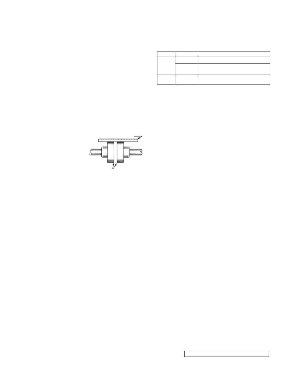
4. Align the low speed shaft coupling half with the coupling
half on the pump or driver shaft. Use a straight edge to
align the coupling as in figure 6. A C-clamp, clamped over
pieces of keystock, may be used to hold this alignment
until the mounting bracket is securely bolted to the base
plate. It may be necessary to shim the bracket to the
extact center height of the pump or driven shaft. For
additional information on coupling alignment, refer to
Engineering Service Bulletin #ESB 61.
SIzE
RATIO
ChANGES REQUIRED
B
6.27 to 1
Snap ring for pinion and shaft
7.65 to 1
Two spacers ( A larger O.D. than is used
on other ratios) and gear shaft
C
7.95 to 1
Gear shaft and a longer key, also a snap
ring.
NOTE: SNAP RING IS FURNISHED WITH “C” 7.95 TO 1 PINION AND
SHAFT
When changing the reducer ratio, the nameplate should
also be changed to new ratio reducer part number. After
making any output or input speed change (complete reducer
or gear ratio changes), a check should be made to ensure
the couplings are of sufficient size for the conditions which
reducer will be operating. For ratios available see page 1 of
this manual, catalog specification sheet or consult factory or
Viking representative.
DISASSEMBLY
Before starting disassembly, study the exploded view (see
Fig. 7, 8 or 9) for the particular size reducer that is being
disassembled to help determine parts relationship. The parts
are indexed in a logical sequence of disassembly and will
prove to be a valuable aid in dismantling the reducer.
1. Disconnect the couplings and remove the capscrews
holding the mounting bracket to the base. Remove the
coupling halves and bracket from the reducer.
2. Remove the breather and drain plugs. Drain all lubricant
from the reducer.
3. Remove the capscrews from the gear case halves.
4. Tap firmly and alternately on the gear shaft and pinion
shaft. This will separate the reducer halves.
5. With two screwdrivers at opposite sides, carefully pry
the reducer cover loose from internal ball bearings. DO
NOT FORCE. Be careful not to damage the gasket or
gasket surface.
6. Grasp the pinion and gear shafts and pull both
assemblies simultaneously from the case or cover.
7. Use a conventional gear or bearing puller to remover the
bearing from gear shaft. Remove the bevelled spacer on
“B” and “C” size reducers. Press the shaft from the gear.
8. Use a puller and remove bearings from the pinion shaft.
Remove the spacer from “B” size 7.65 to 1 ratio from the
pinion shaft.
9. Remove the lip seals from the gear case halves (cover
and case) only if they show signs of deterioration or
damage. Lip seals must be pressed or driven out
from the inside of gear case and cover on “B” and “C”
reducers. “A” size reducer may have lip seals pressed in
or out from either side of gear case half.
FIGURE 6
COUPLING ALIGNMENT
USE STRAIGHT EDGE. THESE SURFACES MUST BE PARALLEL
CHECK WIDTH BETWEEN THESE SURFACES WITH INSIDE CALIPERS TO BE
CERTAIN THE FACES ARE EQUAL DISTANCE APART AND PARALLEL
5. Rotate the reducer in the “banana” slots of the bracket
until the high speed coupling half is at the exact center
height of the motor coupling half.
6. Securely tighten the reducer to the bracket .
7. Align the high speed shaft coupling and fasten the motor
securely to base plate.
CAUTION ! : DO NOT EXCEED RECOMMENDED MAXIMUM
HORSEPOWER, SEE CATALOG SPECIFICATION SHEET.
DO NOT OPERATE BEFORE ADDING LUBRICANT.
OPERATION
After the first few hours of operation, inspect reducer for
leaks. If leakage between gear case and cover cannot be
stopped by tightening of nuts or capscrews, the gasket
should be replaced. Leakage around either shaft indicates a
damaged lip seal which should be replaced.
The operating temperature on the outside of the reducer
case, after a few hours operation, should not be more than
approximately 75º F higher than surrounding air temperature.
The oil within the Reducer should never exceed 200º F.
Gear Ratios
Four different gear ratios are available for the “A” size
Reducers. Eight ratios are available for “B” size reducers and
seven ratios for “C” size reducers. Complete reducers within
a size may be interchanged on a Viking pump unit to obtain
desired pump speeds and capacities.
Gear ratios may be changed in all reducers within each size
by selecting the proper pinion and gear of a common ratio.
A pinion from one ratio cannot be used with a gear from a
different ratio. Certain “B” and “C” reducers require additional
or different parts besides the pinion and gear to make the
ratio change. See the chart below for changes required.