Maintenance, Special information (cont’d) – Viking Pump TSM344: CMD Mag Drive User Manual
Page 3
SECTION TSM 344
ISSUE
F
PAGE 3 OF 24
MAINTENANCE
DANGER !
Before opening any viking pump liquid
chamber (pumping chamber, reservoir,
relief valve adjusting cap fitting, etc.)
Be sure:
1. That any pressure in the chamber has
been completely vented through the
suction or discharge lines or other
appropriate openings or connections.
2. That the driving means (motor,
turbine, engine, etc.) has been
“locked out” or made non-operational
so that it cannot be started while
work is being done on pump.
3. That you know what liquid the
pump has been handling and the
precautions necessary to safely
handle the liquid. Obtain a material
safety data sheet (MSDS) for the
liquid to be sure these precautions
are understood.
Failure to follow above listed
precautionary measures may result in
serious injury or death.
Series CMD pumps are designed for long, trouble-free
service life under a wide variety of application conditions with
a minimum of maintenance. The following points will help
provide long service life.
Pumps that are mounted directly to the motor will need to be
removed from the mounting bracket to perform mechanical
seal maintenance or replacement.
CLEANING PUMP: Keep the pump as clean as possible.
This will facilitate inspection, adjustment, and repair work.
STORAGE: If pump is to be stored, or not used for six
months or more, the pump must be drained and a light coat
of light oil must be applied to all internal pump parts.
Apply grease to the pump shaft extension. Viking suggests
rotating pump shaft by hand one complete revolution every
30 days to circulate the oil. Tighten all pump assembly bolts
before putting the pump in service after being stored.
PRESSURE RELIEF VALVES:
1. Viking pumps are positive displacement pumps and
must be provided with some sort of pressure protection.
This may be an inline pressure relief valve, a torque-
limiting device, or a rupture disk, or other method.
NOTE: Pump can be operated in reverse direction for
short duration at low differential pressure to clean/flush
out lines.
2. If pump rotation is to be reversed during operation,
pressure protection must be provided on both sides
of the pump.
3. Pressure relief valves cannot be used to control pump
flow or regulate discharge pressure.
For additional information on pressure relief valves,
refer
to Technical Service Manual TSM000 and Engineering
Service Bulletin ESB-31.
SPECIAL INFORMATION (CONT’D)
Viton
®
is a registered trademark of DuPont Performance Elastomers.
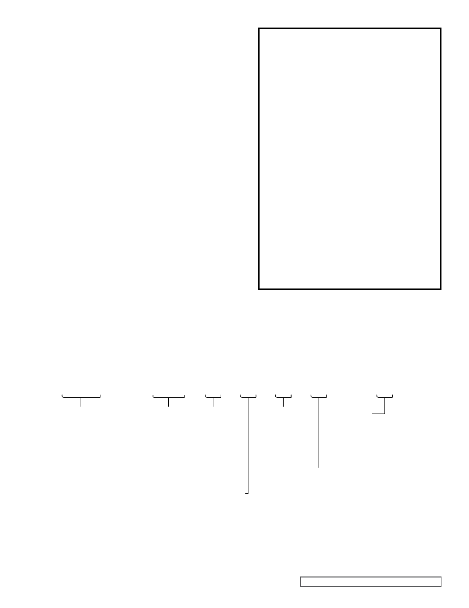
CMD - E02 E L v F - X
Mounting Arrangement:
F = NEMA 56C (E02, E05, E12, E25)
O = NEMA 143TC-182C (E05, E12, E25, E75, E125)
R = NEMA 182TC-184TC (E75, E125)
H = IEC B34 63 (E02, E05, E12)
K = IEC B34 80 (E02, E05, E12)
P = IEC B14 100/112 (E25, E75, E125)
Y = No Motor Mount Kit (E02, E05, E12, E25, E75, E125)
Model:
E02
E05
E12 *
E25 *
E75 *
E125 *
Series:
Composite Mag Drive
Materials/Ports:
E = ETFE, FNPT
(E02, E05, E12)
B = ETFE, ISO 7-1
(E02, E05, E12)
F = ETFE, Flange
(E25, E75, E125)
Bearings:
L = Carbon Graphite
B = Graphite-Impregnated
Silicon-Carbide
O-Rings:
V = Viton
®
E = EPDM
Options:
A = Bearing Flush Ports
B = Combination of Options A and N
N = Without Drive Magnet
X = Complete Pump (No Options)
* Export license required under U.S. Export
Administration ECCN 28350 and 28999.