Viking Pump TSM344: CMD Mag Drive User Manual
Page 11
SECTION TSM 344
ISSUE
F
PAGE 11 OF 24
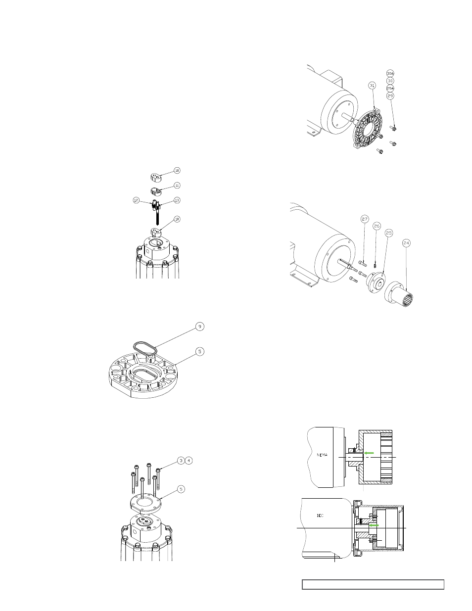
13. Install the spacer O-Ring (item 9) into the front cover
as shown. Some O-Ring lubricant may help keep the
O-Rings in place during assembly.
14. Install the front cover with spacer O-Ring using the six
bolts and washers. Tighten these bolts to the torque
specified on
page 20. Always tighten fasteners in a
progressive “crisscross” pattern.
15. For IEC frame motors only, if it was removed, install the
motor adaptor plate (item 31) onto the motor face using
the four bolts and washers (items 29 and 30). Always
tighten fasteners in a progressive “crisscross” pattern.
16. Secure the magnet hub (item 25) to the drive magnet
(item 24) using the four screws (item 27). Always tighten
fasteners in a progressive “crisscross” pattern.
17. Align the keyway, and slide the drive magnet onto the
motor shaft until the end of the motor shaft aligns with
faces of the drive magnet motor hub, as shown below.
Secure with the setscrew (item 26). Application of a no-
seize compound on the shaft and key will make future
maintenance easier.
18. Complete the assembly by replacing the assembled
pump onto the motor, using care not to allow fingers
to get pinched when the magnets attract. Secure the
pump to the motor with the four bolts and washers
(items 22, 23). Always tighten fasteners in a progressive
“crisscross” pattern.
FIGURE 13
FIGURE 14
FIGURE 15
FIGURE 16
FIGURE 17
9. Insert a bearing (item 10) into the center housing (item
14) and slide to the bottom of the housing. Bearings are
symmetrical and orientation does not matter.
10. Install the housing liner (item 11) and slide until it seats
against the first bearing. Install the idler gear (item
12) into the top hole in the bearing until the gear seats
against the first bearing.
11. Install the drive gear (item 13), splined-end first, into the
assembly until it bottoms out against the bearing. The
shaft may have to be rotated slightly to properly fit the
splined-end into the drive magnet and gear to the idler
gear assembly.
12. Insert the second bearing (item 10) into the housing
bore until it rests against the housing liner. Bearings are
symmetrical and orientation does not matter.
FIGURE 18