Safety relief valve instructions, Caution – Viking Pump TSM320.2: GG-HL 75/475 User Manual
Page 8
SECTION TSM 320.2
ISSUE
F
PAGE 8 OF 9
1. INSTALL THE SEAL SEAT. Lubricate the outside
diameter of the seal seat and the inside of the seal seat
and the inside of the seal housing bore with the light oil
(not grease). Start the seal seat in the casing and press
into place.
To Reassemble Model H475, HJ475, or HL475
Mechanical Seal Pumps: see Figure 10)
CAUTION !
Never touch the sealing faces of the me-
chanical seal with anything except fingers
or a clean cloth.
2. INSTALL THE ROTARY MEMBER OF SEAL. Flush the
rotor hub and the inside of the rotary member with light
oil. Slide the spring and rotary member over the rotary
hub only far enough to hold the spring in position. Do not
compress the spring at this time.
3. INSTALL THE ROTOR IN THE CASING.
4. INSTALL THE IDLER. Put the idler with the bushing on
the idler pin.
5. PLACE THE HEAD GASKETS ON THE HEAD. The
proper amount of gaskets should be used to provide
the necessary end clearance within the pump so it turns
freely with no appreciable end play.
Gasket Table 4
gives the normal amount of gaskets used.
6. THE HEAD CAN NOW BE ASSEMBLED ON THE
PUMP. Tilt the head away from the pump slightly until
the crescent enters the inside diameter of the rotor and
rotate the idler until its teeth mesh with the rotor teeth.
Do not damage the head gaskets. Note the correct
position of the idler and crescent.
Refer to Figure 10
and
Disassembly step 2.
PUMP
MODELS
NORMAL
AMOUNT USED
(INCH)
ONE SET OF GASKETS
CONSISTS OF THE
FOLLOWING
H475, HJ475 &
HL475 Mechanical
Seal Pumps
.010” - .015”
2 - .002” Plastic
2 - .006” Paper
GASKET TABLE 4
FIGURE 10
SECTIONAL DRAWING OF MODELS H475, HJ475 & HL475
MECHANICAL SEAL PUMPS
MOUNTING FLANGE
IDLER
HEAD
CRESCENT
ROTOR
SEAL SEAT
SPRING
ROTARY
MEMBER
SAFETY RELIEF VALVE
INSTRUCTIONS
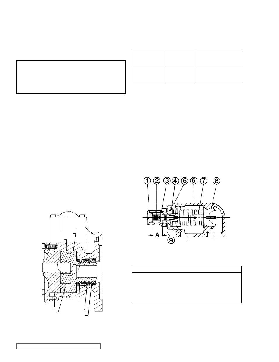
FIGURE 11
PRESSURE RELIEF VALVE - G, GG, H, HJ & HL SIZE
VALVE - LIST OF PARTS
1. Valve Cap
6. Valve Body
2. Adjusting Screw Cap
7. Valve Spring
3. Lock Nut
8. Poppet
4. Spring Guide
9. Cap Gasket
5. Bonnet
7. CHECK THE PUMP END CLEARANCE. Measure
the clearance between the back of the rotor and the
machined surface in the bottom of the casing by inserting
a feeler gauge through the port opening. This is the end
clearance; normal amount is 0.003” and 0.005”. Add or
remove gaskets until the figure is reached.
8. BOLT THE VALVE INTO THE CASING. Place the valve
gasket and valve or coverplate on the pump and fasten
securely with the four capscrews.
9. ASSEMBLE THE PUMP ON THE MOTOR. Install the
length key in the keyway in the motor shaft.
NOTE: Key must be full length to avoid misalignment
of the pump, which could cause serious damage to the
pump. Slide the pump on the motor shaft and fasten
securely with the four capscrews.