Maintenance – Viking Pump TSM320.2: GG-HL 75/475 User Manual
Page 3
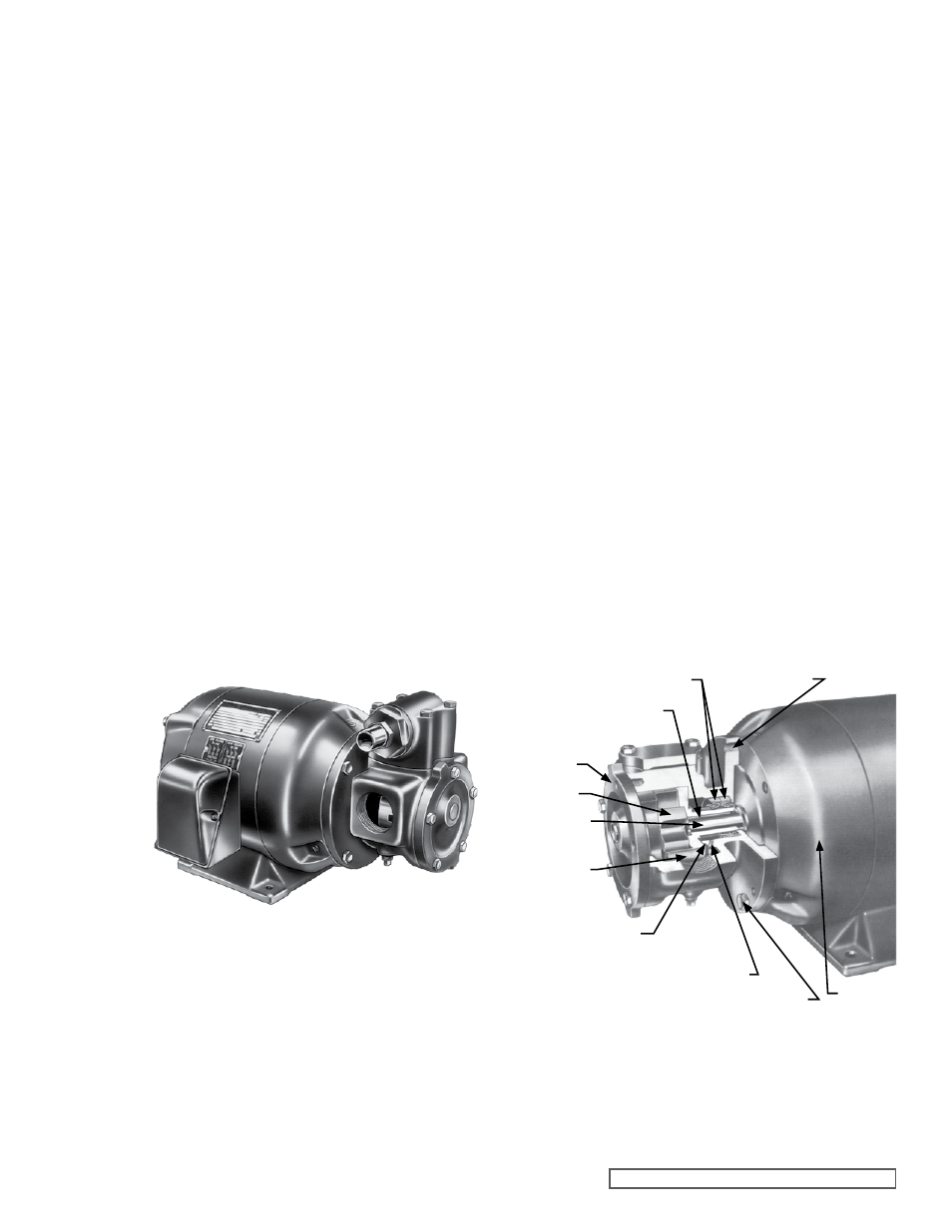
FIGURE 3
CUTAWAY OF H, HJ AND HL 75
LIP SEAL PUMPS
ROTOR
MOTOR KEY
CHECK END
CLEARANCE
MOUNTING
CAPSCREW
JACKSCREW
HOLE
LIP SEALS (2)
SUCKBACK SCREW
MOTOR
HEAD
IDLER
MOTOR
SHAFT
SECTION TSM 320.2
ISSUE
F
PAGE 3 OF 9
PRESSURE RELIEF VALVES:
1. Viking pumps are positive displacement pumps and
must be provided with some sort of pressure protection.
This may be a relief valve mounted directly on the pump,
an inline pressure relief valve, a torque limiting device or
a rupture disk.
2. This series of pumps may be equipped with an integral
pressure relief valve. Standard configuration is for
clockwise rotation.
3. If pump rotation is reversed during operation, pressure
protection must be provided on
both sides of the pump.
4. Relief valve adjusting screw cap must always point
towards the suction side of the pump.
5. Pressure relief valves should not be used to control
pump flow or regulate discharge pressure.
For additional information on pressure relief valves,
Refer
to Technical Service Manual TSM000 and Engineering
Service Bulletin ESB-31.
NOTE: Lip seal pumps, Models G75, GG75, H75, HJ75,
HL75, G75M, GG75M, H75M, HJ75M and HL75M are
equipped with an internal suckback arrangement. A small
suckback screw (self-locking) is inserted in a hole on the
discharge side of the pump. This can be seen through
the port opening and behind the rotor
(refer to figure 3).
The hole on the suction side must be left open to prevent
damage to the lip seals. Both holes are plugged in the
mechanical seal pump Model G475, GG475, H475, HJ465,
HL475, G475M, GG475M, H475M, HJ475M, and HL475M.
Since these pumps have only two moving parts and are
all performance tested at the factory, they seldom cause
trouble. If trouble does occur we always advise investigating
all other possible causes before disassembling the pump.
Most troubles are caused by air leaks and obstruction in
the suction line.
MAINTENANCE
The Series 75 and 475 pumps are designed for long trouble
free life under a wide variety of application conditions with
minimum maintenance, however, the following should be
considered:
1. LUBRICATION – External lubrication is not required for
this series of pumps. The liquid being pumped lubricates
the internal bearings in the pump.
FIGURE 2
MOTOR MOUNTED PUMP SHOWING
H, HJ AND HL SIZE
2. END CLEARANCE ADJUSTMENT – After long term
operation it is sometimes possible to improve the
performance of the pump, without major repair, by
adjusting the end clearance.
Refer to ASSEMBLY, page
4, for information regarding this procedure.
3. PRESSURE RELIEF VALVE – If your pump is equipped
with a pressure relief valve, adjustment can be made
as follows. Remove the adjusting screw cap, turn in the
adjusting screw to increase the pressure and turn-out to
decrease the pressure. If the pump is not producing the
rated capacity, adjustment of the pressure relief valve
may be necessary. Be sure the adjusting screw cap is
re-installed before the pump is started.
4. CLEANING THE PUMP – It is good practice to keep the
pump as clean as possible. This will facilitate inspection,
adjustment and repair work.
5. STORAGE – If the pump is to be stored or not used for
any appreciable length of time it should be drained and
a light coat of lubricating and preservative oil should be
applied to the internal parts
SUGGESTED REPAIR TOOLS: The following tools must be
available to properly repair Series 75 and 475 pumps. These
tools are in addition to standard mechanics’ tools such as
open end wrenches, pliers, screw drivers, etc. Most of the
items can be obtained from an industrial supply house.
1. Soft headed hammer
2. Allen wrenches (some mechanical seals and set collars)
3. Mechanical seal installation sleeve
4. Brass bar
5. Arbor press