Assembly disassembly – Viking Pump TSM320.2: GG-HL 75/475 User Manual
Page 4
SECTION TSM 320.2
ISSUE
F
PAGE 4 OF 9
1. REMOVE THE PUMP FROM THE MOTOR. Remove
the four capscrews and use three as jackscrews in the
threaded holes of the pump from the motor shaft.
NOTE: If the pump has a valve, it must be removed first
to have room for the jackscrews.
2. REMOVE PUMP HEAD.
NOTE: Mark the head and casing before disassembly
to make sure they are reassembled properly. The idler
pin, which is offset in the pump head, should be properly
positioned toward and equal distance between the port
connections to allow for proper flow of liquid through the
pump.
If it is necessary to disassemble the pump for inspection
or repair, first remove the head capscrews and remove
head by tapping the head removing lugs lightly.
3. REMOVE THE HEAD GASKETS. If a new set is not
available, the original gaskets may be reused provided
they are not damaged.
4. REMOVE THE IDLER FROM THE IDLER PIN. If the
idler pin is worn, the head, idler pin and idler bushing
should all be replaced.
If the idler bushing is worn, a new bushing is needed.
If the new bushing is carbon graphite, special care must
be taken when pressing it into the idler. An arbor press
should always be used; be sure the bushing is started
straight.
DO NOT STOP the pressing operation until
the bushing is in its proper location. Carbon graphite
is brittle; starting and stopping the pressing operation
Reassembly of these pumps is explained by one of the
following sets of instructions. Follow the instructions for the
proper pump model.
Before starting to reassemble the pump, clean all parts
thoroughly and replace those which show signs of excessive
wear or damage.
ASSEMBLY
DISASSEMBLY
DANGER !
Before opening any Viking pump liquid
chamber (pumping chamber, reservoir,
relief valve adjusting cap fitting, etc.)
Be sure:
1. That any pressure in the chamber has
been completely vented through the
suction or discharge lines or other
appropriate openings or connections.
2. That the driving means (motor,
turbine, engine, etc.) has been “locked
out” or made non-operational so that
it cannot be started while work is
being done on pump.
3. That you know what liquid the
pump has been handling and the
precautions necessary to safely
handle the liquid. Obtain a material
safety data sheet (MSDS) for the
liquid to be sure these precautions
are understood.
Failure to follow above listed
precautionary measures may result in
serious injury or death.
To Reassemble Model G75 or GG75
Lip Seal Pumps: see Figure 5)
1. INSTALL THE LIP SEALS. The lip seals should be
installed in the casing one at a time from the large
flanged end. The sealing lips must face away from each
other.
NOTE: Use an arbor press with an arbor of 2.188
diameter and press the lip seals in the casing as far
as they will go.
See figures 7, 8, 9, and 10 for a cross
section of your pump models.
2. LUBRICATE THE LIP SEALS. Fill the area between the
lips of the lip seals with grease.
3. INSTALL THE ROTOR. Flush the rotor hub with light oil
(not grease) and insert the rotor in the casing with the
hub through the lip seals.
frequently results in a cracked bushing. If cracked in the
idler, the bushing will quickly disintegrate.
5. REMOVE THE ROTOR FROM THE CASING. The rotor
of the two smaller pumps (G & GG sizes) can be removed
by pressing on the end of hollow drive end of the rotor. It
will be necessary on the models with mechanical seals
(G475 & GG475) to use an arbor press and an arbor of
approximately 1.375” diameter. The seal will remain in
the casing.
The rotor of the three larger size pumps (H, HJ, HL
sizes) can also be removed by pushing on the hollow
drive end of the rotor. The spring and rotary member of
the mechanical seal will come out with the rotor in these
pumps.
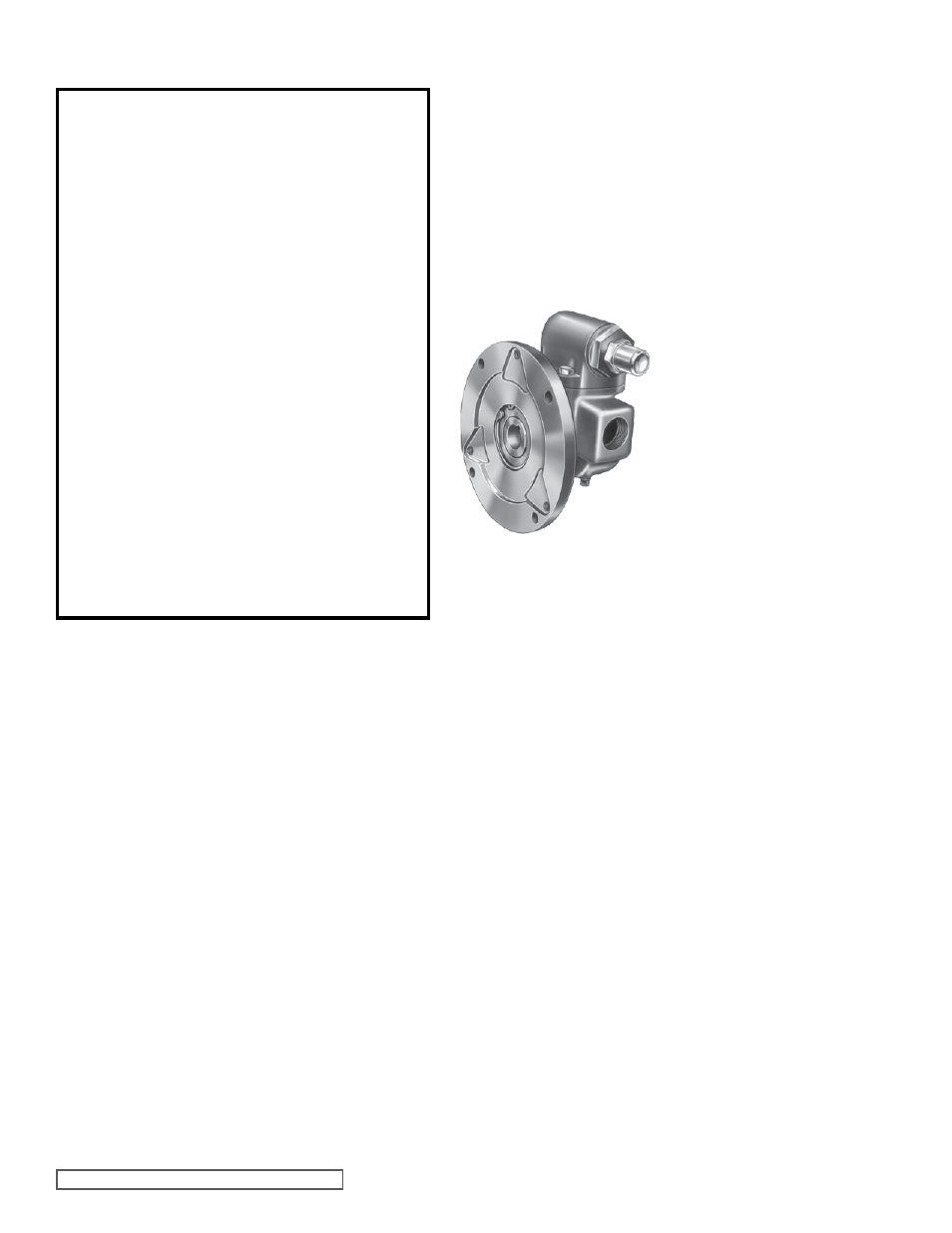
FIGURE 4
VIEW OF FLANGE END
OF G AND GG475
MECHANICAL SEAL PUMPS
6. REMOVE THE MECHANICAL SEAL OR LIP SEALS.
(See figure 4) Remove the snap ring in the casing of the
two smaller pumps (G and GG sizes) and the complete
seal can be removed out of the large flanged end of the
casing.
Remove the spring and rotary member from the rotor
and the seal seat or lip seals from the pump end of the
casing of the three larger size pumps (H, HJ, HL).