Caution – Viking Pump TSM320.2: GG-HL 75/475 User Manual
Page 7
SECTION TSM 320.2
ISSUE
F
PAGE 7 OF 9
PUMP
MODELS
NORMAL
AMOUNT USED
(INCH)
ONE SET OF GASKETS
CONSISTS OF THE
FOLLOWING
G75 and GG75
Lip Seal Pumps
.010” - .015”
2 - .005” Plastic
3 - .002” Plastic
GASKET TABLE 2
PUMP
MODELS
NORMAL
AMOUNT USED
(INCH)
ONE SET OF GASKETS
CONSISTS OF THE
FOLLOWING
G75 and GG75
Lip Seal Pumps
.010” - .015”
2 - .005” Plastic
3 - .002” Plastic
GASKET TABLE 3
CAUTION !
Be sure the adjusting screw of the relief
valve points toward the suction port.
To Reassemble Model G475 or GG475
Mechanical Seal Pumps: see Figure 9)
1. INSTALL THE ROTOR IN THE CASING.
2. INSTALL THE IDLER. Put the idler with bushing on the
idler pin.
3. PLACE THE HEAD GASKET ON THE HEAD. The
proper amount of gaskets should be used to provide
the necessary end clearance within the pump so it turns
freely with no appreciable end play.
Gasket Table 3
gives the normal amount of gaskets used.
4. THE HEAD CAN NOW BE ASSEMBLED ON THE
PUMP. Tilt the top of the head away from the pump
slightly until the crescent enters the inside diameter of
the rotor and rotate the idler until its teeth mesh with the
rotor teeth. Do not damage the head gaskets.
Note the correct position of the idler and crescent (
See
Figure 9 and Disassembly Step 2). Tighten the head
capscrews and then check the end clearance.
5. CHECK THE PUMP END CLEARANCE. Measure
the clearance between the back of the rotor and the
machined surface in the bottom of the casing by inserting
the feeler gauge through the port opening. This is the
end clearance. Normal amount is 0.003” to 0.005”. Add
or remove gaskets until the figure is reached.
CAUTION !
Never touch the sealing faces of the me-
chanical seal with anything except fingers
or a clean cloth.
9. ASSEMBLE THE PUMP ON THE MOTOR. Install the
full length key in the keyway of the motor shaft.
NOTE: Key must be full length to avoid misalignment of
the pump rotor, which could cause serious damage to
the pump. Slide the pump on the motor shaft and fasten
securely with the four capscrews.
8. BOLT THE VALVE TO THE CASING. Place the valve
gasket and valve or coverplate on the pump and fasten
securely with the four capscrews.
6. INSTALL THE MECHANICAL SEAL. Slide the seal
spring washer over the rotor hub as far as it will go. Flush
the rotor hub and seal housing bore with light oil (not
grease) and assemble the spring, rotary member and
seat of the mechanical seal in position,
refer to Figure 9.
7. INSTALL THE SNAP RING. Install the snap ring in the
groove in the casing. This will hold the seal at its proper
working length.
8. BOLT THE VALVE TO THE CASING. Place the valve
gasket and valve or coverplate on the pump and fasten
securely with the four capscrews.
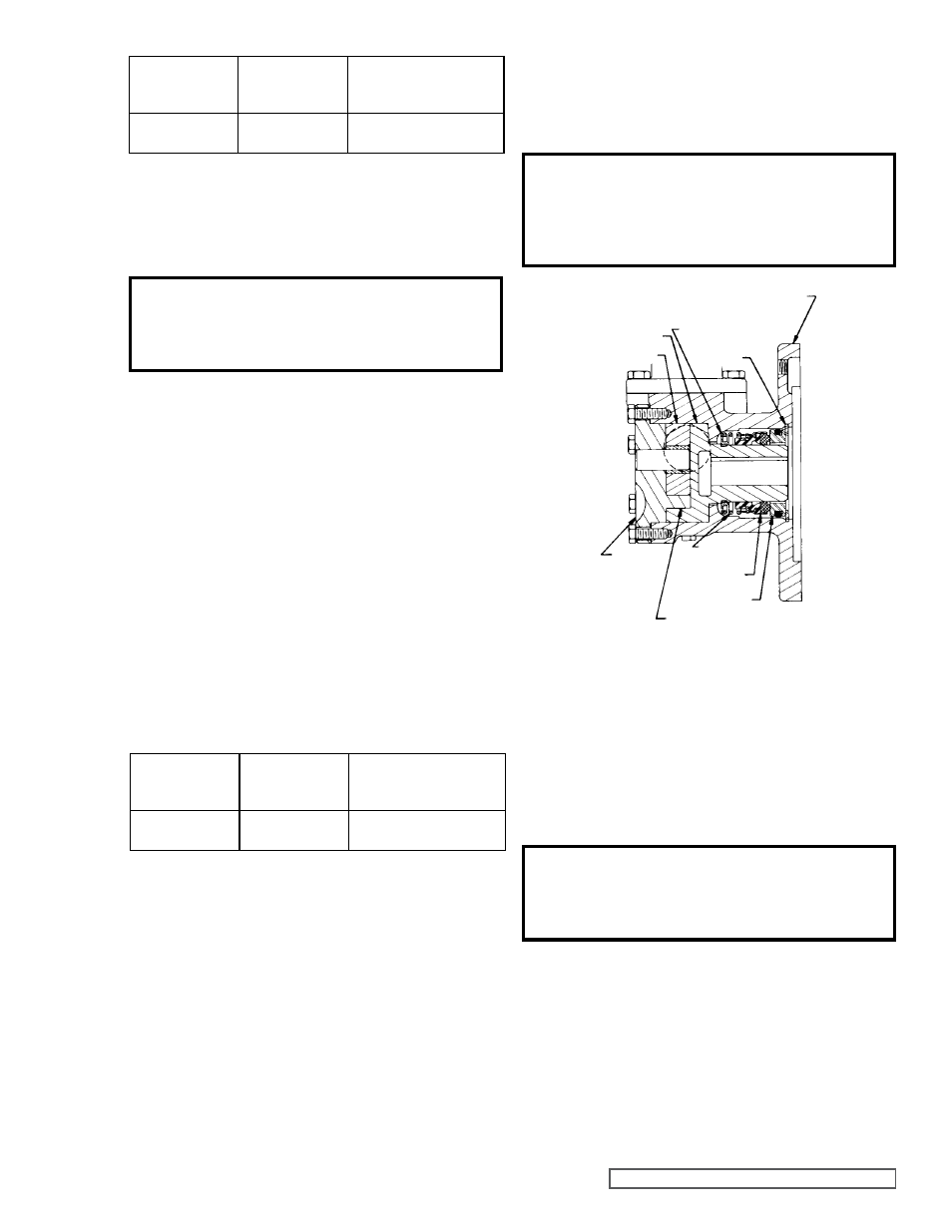
FIGURE 9
SECTIONAL DRAWING OF MODELS G475 & GG475
MECHANICAL SEAL PUMPS
MOUNTING FLANGE
IDLER
HEAD
CRESCENT
ROTOR
SEAL SEAT
SEAL SPRING
WASHER
SPRING
SNAP
RING
ROTARY
MEMBER
CAUTION !
Be sure the adjusting screw of the relief
valve points toward the suction port.
9. ASSEMBLE THE PUMP ON THE MOTOR. Install the
full length key in the key way of the motor shaft.
NOTE: Key must be full length to avoid misalignment
of the pump, which could cause serious damage to the
pump. Slide the pump on the motor shaft and fasten
securely with the four capscrews.