Caution – Viking Pump TSM320.2: GG-HL 75/475 User Manual
Page 5
SECTION TSM 320.2
ISSUE
F
PAGE 5 OF 9
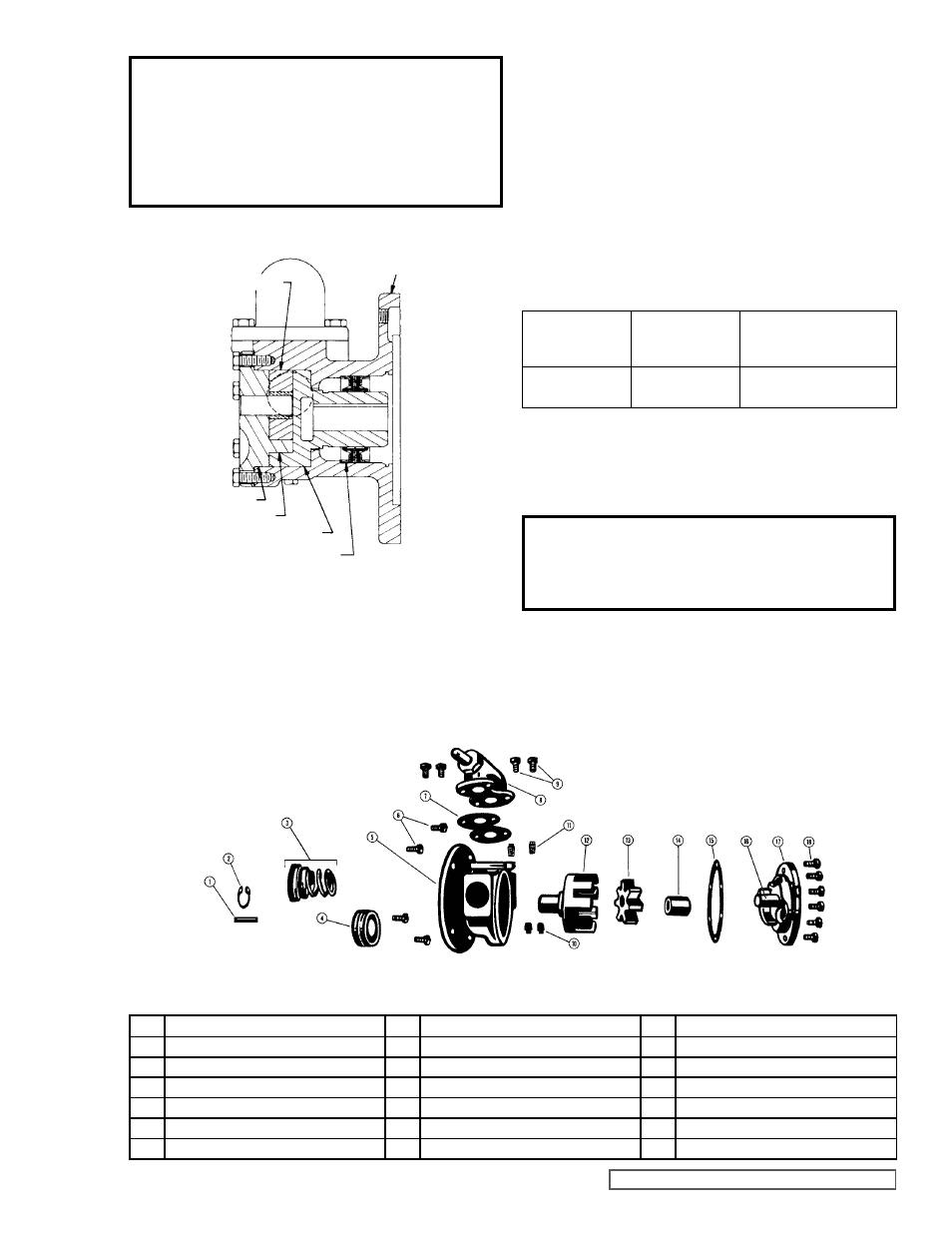
FIGURE 6
EXPLODED VIEW SERIES 75 & 475 PUMPS (G AND GG SIZE)
ITEM
NAME OF PART
ITEM
NAME OF PART
ITEM
NAME OF PART
1
Key for Motor Shaft (Full Length)
7
Gasket for Relief Valve or Cover Plate
13
Idler
2
Snap Ring (Mech. Seal Pumps Only)
8
Relief Valve
14
Idler Bushings
3
Mechanical Seal (Complete)
9
Capscrews for Relief Valve or Cover Plate
15
Gasket for Head
4
Lip Seal (2)
10
Pipe Plugs - 1/8”
16
Idler Pin
5
Casing
11
Machine Screw (2-Mech. Seal, 1-Lip Seal)
17
Head
6
Capscrews (Pump on Motor)
12
Rotor
18
Capscrews for Head
CAUTION !
Turn the rotor back and fourth as you
exert enough force to push it through the
lip seal and to the bottom of the casing.
Be careful not to fold under the lip of the
inner seal.
FIGURE 5
SECTIONAL DRAWING OF MODELS G75 & GG75
LIP SEAL PUMPS
MOUNTING FLANGE
IDLER
HEAD
CRESCENT
ROTOR
LIP SEALS (2)
4. INSTALL THE IDLER. Put the idler with the bushings on
the idler pin.
CAUTION !
Be sure the adjusting screw of the relief
valve points toward the suction port.
PUMP
MODELS
NORMAL
AMOUNT USED
(INCH)
ONE SET OF GASKETS
CONSISTS OF THE
FOLLOWING
G75 and GG75
Lip Seal Pumps
.010” - .015”
2 - .005” Plastic
3 - .002” Plastic
GASKET TABLE 1
6. THE HEAD CAN NOW BE ASSEMBLED ON THE
PUMP. Tilt the top of the head away from the pump
slightly until the crescent enters the inside diameter of
the rotor and rotate the idler until its teeth mesh with
the rotor teeth. Do not damage the head gaskets. Note
correct position of the idler and crescent
(See Figure 5
and
Disassembly step 2). Tighten the head capscrews
and then check the end clearance.
7. CHECK PUMP END CLEARANCE. Measure the
clearance between the back of the rotor and the
mechanical surface in the bottom of the casing by
inserting a feeler gauge through the port opening. This is
the end clearance; the normal amount is 0.003” to 0.005”.
Add or remove gaskets until the figure is reached.
8. BOLT THE VALVE INTO THE CASING. Place the valve
gasket and valve or cover-plate on the pump and fasten
securely with the four capscrews.
5. PLACE HEAD GASKETS ON THE PUMP HEAD. The
proper amount of gaskets should be used to provide
necessary end clearance within the pump so it turns
freely with no appreciable end play.
Gasket Table 1
gives the normal amount of gaskets used.
9. ASSEMBLE THE PUMP ON THE MOTOR. Install the
full length key in the keyway of the motor shaft.
NOTE: Key must be full length to avoid misalignment of
the pump rotor, which could cause serious damage to
the pump. Slide the pump on the motor shaft and fasten
securely with the four capscrews.