Cb a, Danger – Viking Pump TSM163: N-R 337/4337 User Manual
Page 7
SECTION TSM 163
ISSUE
D
PAGE 7 OF 15
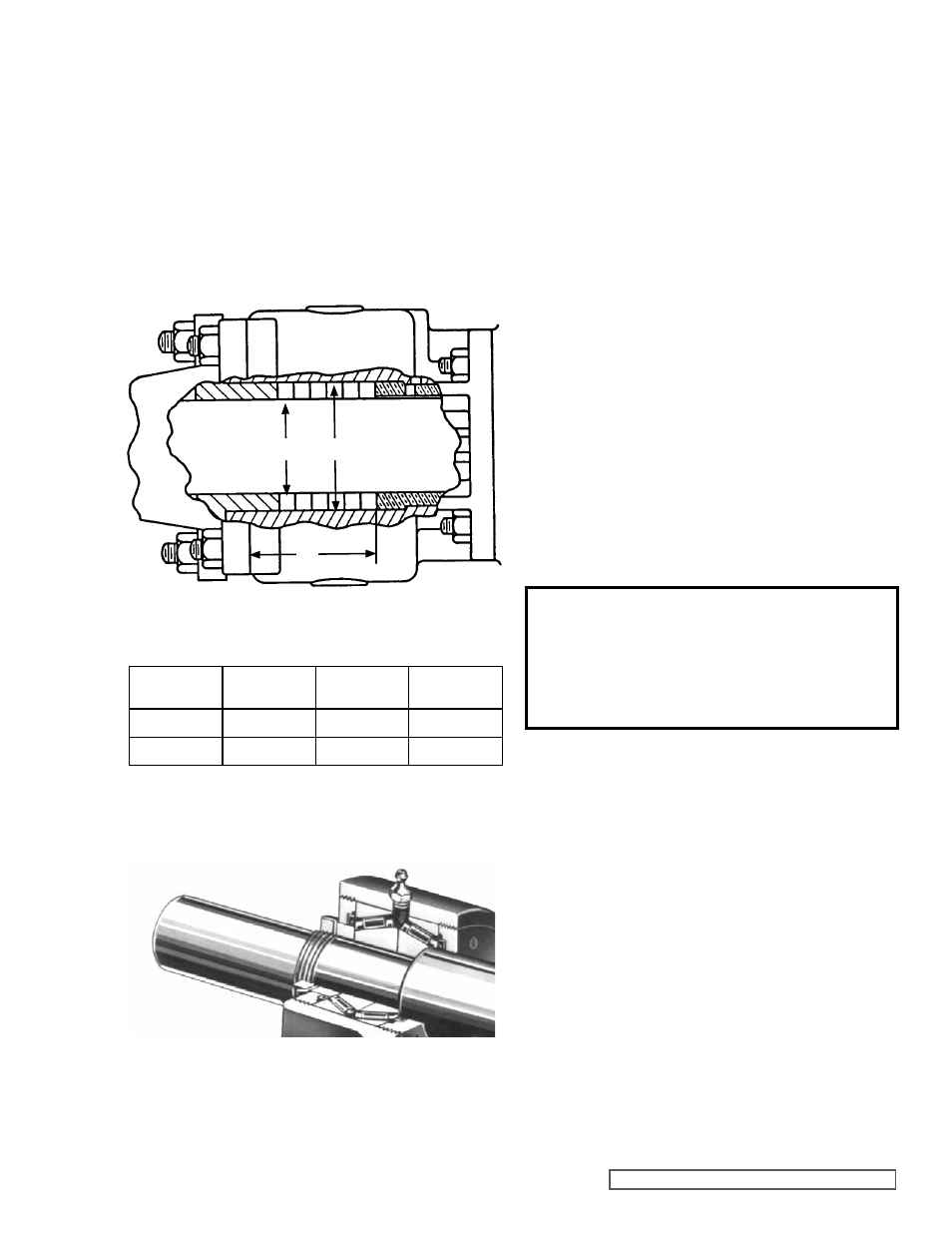
FIgURE 8
STUFFINg BOX DIMENSIONS
7. Push the rotor back against the head.
8. Install the drain plug in the casing.
9. Place packing retainer washer in bottom of packing
chamber and pack pump with new packing. Use packing
suitable for liquid being pumped. Install packing,
staggering the joints from one side of the shaft to the
other. Lubricate packing rings with oil, grease or graphite
to aid assembly. A length of pipe will help to seat each
packing ring.
Refer to Figure 8 below.
10. Install the thrust bearing housing on the end of rotor ring
sleeve and tighten the nuts and capscrews securely. It is
not necessary to use gasket between these parts.
PUMP
MODEL
A
(INCH)
B
(INCH)
C
(INCH)
N337
4.63”
4.69”
3.44”
R337
4.63”
4.69”
3.44”
c
B
a
DANgER !
Before starting pump, be sure all drive
equipment guards are in place.
Failure to properly mount guards may
result in serious injury or death.
FIgURE 9
11. Insert both tapered roller bearings in the thrust bearing
housing, large end of inner races together. It is possible
to install bearings incorrectly, for proper assembly
refer
to Figure 9 below.
12. Install the bearing spacer collar on the shaft next to the
inner race of the roller bearing.
13. Turn the inner end cap into the thrust bearing housing
just far enough to hold in place.
Install the outer end cap and turn in approximately half
way.
14. Insert a length of hardwood or brass bar through the port
opening between the rotor teeth to keep the rotor from
turning.
15. Install the lockwasher placing tang in the keyway on the
shaft. Tighten the locknut to 170-190 ft – lbs. Torque.
Bend one tang of lock washer into slot of locknut. If tang
does not line up with slot tighten lock nut until it does.
Failure to tighten locknut or engage the lock washer tang
could result in early bearing failure and cause damage to
rest of pump.
16. Remove the length of hardwood or brass bar from the
port opening.
17. Install the nuts on the packing gland studs and tighten.
Do not over tighten, as it may cause bind on rotor shaft.
18. Reinstall the suckback tubing to the casing and rotor
bearing sleeve.
19. Lubricate all grease fittings with multi-purpose grease,
NLGI #2.
20. Adjust the pump end clearance. Refer to THRUST
BEARINg AND IDLER END CLEARANCE
ADjUSTMENT, page 12.