Disassembly – Viking Pump TSM163: N-R 337/4337 User Manual
Page 5
SECTION TSM 163
ISSUE
D
PAGE 5 OF 15
jACKSCREWS
DISASSEMBLY
DANgER !
Before opening any Viking pump liquid
chamber (pumping chamber, reservoir,
relief valve adjusting cap fitting, etc.)
Be sure:
1. That any pressure in the chamber has
been completely vented through the
suction or discharge lines or other
appropriate openings or connections.
2. That the driving means (motor,
turbine, engine, etc.) has been “locked
out” or made non-operational so that
it cannot be started while work is
being done on pump.
3. That you know what liquid the
pump has been handling and the
precautions necessary to safely
handle the liquid. Obtain a material
safety data sheet (MSDS) for the
liquid to be sure these precautions
are understood.
Failure to follow above listed
precautionary measures may result in
serious injury or death.
1. Mark the head and casing before disassembly to ensure
proper reassembly. The idler pin, which is offset in pump
head, must be positioned towards and equal distance
between the port connections to allow for proper flow of
liquid through pump.
It is not necessary to remove relief valve to take head
off pump; however, removing relief valve will lessen total
weight of part. Do not use chain or cable around relief
valve body to support the head during removal.
For
PRESSURE RELIEF VALVE INSTRUCTIONS, refer to
page 14.
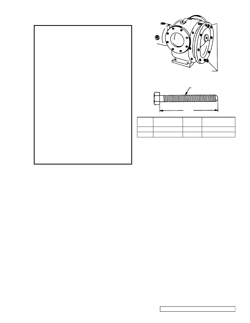
Remove nuts from the head. Jackscrews should be
used to back head away from casing. Refer to figure 5.
Proper size and length of jackscrews for pump size are
shown in
figure 6. The use of a hoist to support head will
facilitate its removal.
Back the head away from casing. Remove the head from
pump. Do not allow the idler to fall from the idler pin. To
prevent this, tilt the top of head back when removing. If a
hoist is not available, cribbing or blocking can be used to
support head. This will eliminate having to lift head into
position when reassembling pump.
2. Remove the head gasket, idler and bushing assembly.
3. Remove the pipe plug from the drain hole in the casing,
this breaks the vacuum behind rotor.
4. Remove the packing gland nuts and slide the gland out
of the rotor bearing sleeve.
FIgURE 5
THREAD SIZE
a
FIgURE 6
MINIMUM LENgTH OF jACK SCREWS
PUMP
SIZE
NO. SCREWS
USED
a
THREAD SIZE
(INCH)
N
2
4.00
0.50” - 13 NC
R
2
4.50
0.63” - 11 NC
5. Insert length of hard wood or brass bar through the port
opening between the rotor teeth to keep the shaft from
turning.
6. Bend the tang on the lock washer up and with a spanner
wrench; remove locknut and lockwasher from the shaft.
Refer to figure 7, page 6.
7. Remove the length of hardwood or brass bar from the
port opening.
8. Cushion the end of the shaft with a hardwood block or
piece of block and drive the rotor out of casing, being
careful to avoid damaging the rotor bearing sleeve
bushing. Support the weight of rotor with a hoist. A cable
sling can be used around the shaft, or around rotor teeth,
to carry weight of the part.
9. Loosen the end cap lockscrews, disengage the end cap
locks and with a spanner wrench remove the end caps.
Remove the roller bearings.
10. Remove the nuts and capscrews and take off the thrust
bearing housing. Remove the packing from the rotor
bearing sleeve.
11. Check the rotor bearing sleeve bushing while the rotor
bearing sleeve is mounted on the casing. If worn, the
bushing must be replaced. Remove the rotor bearing
sleeve from casing. A press must be used to remove the
old bushing. If bushing has a shoulder on the stuffing box
end, it must be pressed out from the packing end of rotor
bearing sleeve. If bushing is carbon graphite,
refer to
INSTALLATION OF CARBON gRAPHITE BUSHINgS,
page 13.