Assembly – Viking Pump TSM163: N-R 337/4337 User Manual
Page 10
9. Loosen the end cap lockscrews, disengage the end cap
locks and with a spanner wrench, remove the end caps.
Examine the lipseal and replace if worn.
Remove the roller bearings.
10. Remove the nuts and capscrews and take off thrust
bearing housing.
11. Check the rotor bearing sleeve bushing while the rotor
bearing sleeve is mounted on the casing. If worn, the
bushing must be replaced.
A press must be used to remove the old bushing. If
the bushing has a shoulder on the stuffing box end, it
must be pressed out from the mechanical seal end of
the rotor bearing sleeve. Carbon graphite bushings are
standard for model 4337 pumps. To replace carbon
graphite bushings,
refer to INSTALLATION CARBON
gRAPHITE BUSHINgS, page 13.
12. Clean all parts thoroughly and examine for wear and
damage. If lipseal replacement is needed, press in the
end cap with the lip facing the end of the shaft. Check
the idler bushing and idler pin, replace if necessary.
If the idler pin is to be replaced, the oil grove on the pin
must be installed facing the center of the crescent on
the head.
If the idler bushing is to be replaced, a press must be used
to move the old bushing and install new. The bushing
position after being pressed in should be flush with
the face of the idler. For carbon graphite idler bushing,
refer to INSTALLATION OF CARBON gRAPHITE
BUSHINgS, page 13.
NOTE: R size idler bushings are shrink fit
13. Wash the bearing in clean solvent. Blow out bearings
with compressed air. Do not allow bearings to spin; turn
the bearing slowly by hand. Spinning the bearings will
damage the race and rollers. Make sure the bearings are
clean, then lubricate with non-detergent SAE 30 weight oil
and check for roughness. Roughness can be determined
by turning the outer race by hand.
CAUTION: do not
intermix the inner and outer races for the roller bearings.
14. Examine the casing for wear. Check the condition of the
casing at the seal area (surface between suction and
discharge ports). If the surface is in good condition, the
casing need not be replaced. When making major repairs,
such as replacement of a rotor, it is usually considered
advisable to install a new head and idler. When making
minor repairs, when only an idler bushing and idler pin
are required, other new parts are usually not necessary.
15. Inspect the mechanical seal for wear or damage. Refer
to figure 14 for mechanical seal list of parts. In general, if
the pump has been operated long enough to exhibit other
worn parts, it is likely the seal will have to be replaced.
Replacing individual seal parts is not recommended, i.e.,
a used seal washer will not perform satisfactorily when
run against a new stationary seat.
SECTION TSM 163
ISSUE
D
PAGE 10 OF 15
SHAFT
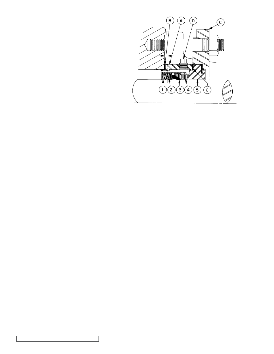
FIgURE 14
PTFE Fitted Mechanical Seal Assembly
For Models N-R4333, 4335 & 4337
1. Retainer Cartridge
2. Springs
3. PTFE Shaft Ring (wedge)
4. Rotating Face (washer)
5. Stationary Seal Seat
6. Seat Gaskets
Seal Mounting Parts
A. Packing box extension
B. Packing box extension gasket
C. Seal plate
D. Flush openings
ASSEMBLY
(PTFE Fitted Type)
Prepare all parts for reassembly ahead of time. Pack roller
bearings with multi-purpose grease, NLGI # 2 and have all
new gaskets on hand.
Three components are furnished in mechanical seal
assembly:
Refer to figure 14, item numbers 1 thru 6.
1. The rotating assembly in which a retainer cartridge
encloses a spring loaded PTFE shaft ring and polished
rotating face. Set screws located around the outside of
the retainer cartridge are provided for securing rotating
assembly to pump shaft.
2. The stationary seal seat.
3. Two seal seat gaskets.
Three pump parts necessary for mounting PTFE mechanical
seal are illustrated in
figure 14, item letters A, B, C and D.
1. The packing box extension has a machine pilot on the
end for installation in the rotor bearing sleeve and two
tapped holes for the seal flush.
2. The packing box extension gasket.
3. The seal plate is machined to accept seal seat and
gasket.