Thrust bearing adjustment, Installation of carbon graphite bushings, Danger – Viking Pump TSM164: GG-AL 4197 User Manual
Page 8
SECTION TSM 164
ISSUE
F
PAGE 8 OF 10
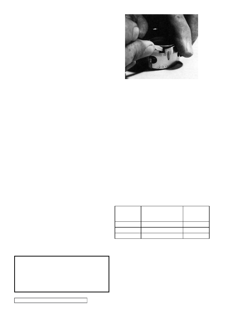
fIgURE 13
Loosen the two screws in the face of the thrust bearing
assembly.
If the shaft cannot be rotated freely, turn the thrust bearing
assembly counterclockwise until the shaft can be turned
easily.
To set end clearance:
1. While turning the rotor shaft, rotate the thrust bearing
assembly clockwise until a noticeable drag occurs. This
is zero end clearance.
2. Mark the position of the bearing housing with respect to
the casing.
3. Rotate the thrust bearing assembly counterclockwise the
distance listed below as measured on outside of bearing
housing.
4. After the adjustment is made, tighten the two setscrews
in the face of the bearing housing assembly to secure
the position.
For viscosities above 2500 SSU, add additional end
clearance (0.004” for GG, HJ and HL size pumps and
0.005” for AS, AK and AL size pumps).
THRUST BEARINg ADJUSTMENT
See
figures 7 and 8, page 6.
PUMP
SIZE
DISTANCE IN INCHES
ON O.D. Of BEARINg
HOUSINg
END
CLEARANCE
GG
0.69” (11/16”)
.005
HJ , HL
0.94” (15/16”)
.005
AS , AK , AL
1.25” (1-1/4”)
.008
4. Tighten
the head capscrews evenly.
5. If
the pump was equipped with a relief valve and was
removed during disassembly, install on the head with
new gaskets. Relief valve adjusting screw cap must
always point towards the suction port. Refer to
figure
3, page 3. For relief valve repair or adjustments, see
“Pressure Relief Valve Instructions,” page 9.
In 2005, the use of single seal bearings were phased out.
Pumps now use “Sealed for Life” bearings that have seals on
both sides. The new bearings can be installed either side first
and do not need to be packed with grease.
6. Install the single row ball bearing in the casing. (For
older models using single seal bearings, pack the ball
bearing with multi-purpose grease, NLGI #2, and install
in the casing with the sealed end towards the head end
of the pump.) Install the inner snap ring in GG, HJ and
HL size pumps. See
figure 7, page 6.
NOTE: AS, AK and AL size pumps do not have a snap
ring; a bearing retainer washer must be assembled over
the end of the shaft before the bearing is assembled.
See
figure 8, page 6.
7. Place
the bearing spacer over the shaft and against the
single row ball bearing in the casing (AS, AK and AL size
pumps). See
figure 8, page 6.
8. Install
the shaft snap ring in the groove in the shaft (GG,
HJ and HL size pumps). See
figure 7, page 6.
9. For models using single seal bearings, pack the
lubrication chamber between the inner ball bearing and
the double row ball bearing in the thrust bearing assembly
approximately half full with multi-purpose grease, NLGI
#2. See
figures 7 and 8, page 6.
10. Pack the double row ball bearing with multi-purpose
grease, NLGI #2 and press into the bearing housing with
shield side toward the coupling end of the shaft. See
figure 7, page 6. (AS, AK and AL size pumps do not
use a shielded bearing). Install the snap ring to hold the
bearing in place on GG, HJ and HL size pumps.
NOTE: On AS, AK and AL size pumps, install the lip seal
in the bearing housing end of the cap. The lip should
face towards the end of the shaft. Put the bearing spacer
sleeve in the lip seal and install in the bearing housing
and tighten the setscrews securely. See
figure 8, page 6.
11. Insert a piece of brass or hard wood through the port
opening between the rotor teeth to keep the shaft from
turning.
12. Start the thrust bearing assembly into the casing. Turn
by hand until tight. This forces the rotor against the head.
Replace and tighten the locknut on the shaft.
13. Remove brass piece or hardwood from port opening
14. Adjust the pump end clearance, refer to “Thrust Bearing
Adjustment” below.
DANgER !
Before starting pump, be sure all drive
equipment guards are in place.
failure to properly mount guards may
result in serious injury or death.
When installing the carbon graphite bushings, extreme care
must be taken to prevent breaking. Carbon graphite is a brittle
material and is easily cracked. If cracked, the bushing will
quickly disintegrate. Using a lubricant and adding a chamfer
on the bushing and the mating part will help in installation.
The additional precautions listed below must be followed for
proper installation:
INSTALLATION Of CARBON
gRAPHITE BUSHINgS