Assembly, Caution – Viking Pump TSM164: GG-AL 4197 User Manual
Page 6
SECTION TSM 164
ISSUE
F
PAGE 6 OF 10
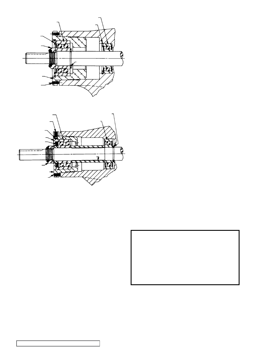
SHAfT SNAP RINg
OUTER
BALL BEARINg
BEARINg
HOUSINg
INNER SNAP RINg
INNER BALL BEARINg
SETSCREW
SHAfT
OUTER
SNAP RINg
LOCKNUT
fIgURE 7
THRUST BEARINg ASSEMBLY gg, HJ AND HL SIZES
fIgURE 8
THRUST BEARINg ASSEMBLY AS, AK AND AL SIZES
BEARINg RETAINER WASHER
BEARINg SPACER
SETSCREW
LOCKNUT
LIP SEAL
END CAP
NYLON INSERT
SHAfT
INNER BALL BEARINg
BEARINg HOUSINg
SETSCREWS
BALL BEARINg
ASSEMBLY
PTfE fitted Mechanical Seal
1. Installing New Seal: See figures 9 thru 13.
GENERAL INFORMATION:
Mechanical seals for HJ, HL, AS, AK and AL4197 size
pumps are of the drive set screw type. Mechanical seals for
GG4197 size pump are friction driven and are pressed onto
the rotor hub.
Installation sleeves are furnished with replacement seals
for GG, AS, AK, size pumps. (this is not necessary with HJ
and HL pumps).
NOTE: Cleanliness during installation is
essential to seal performance. Never allow the seal faces to
contact a dirty surface.
ORDER OF ASSEMBLY:
1. Stationary seat and seat ring in casing
2. Installation sleeve on the shaft (where appropriate)
3. Seal rotating portion on the shaft
4. Rotor and shaft into casing
5. Head with gasket and idler onto the casing
PREPARATION:
Remove burrs from threads and gently radius leading edges
on rotor shaft. Use 300 grit paper to radius the edges and to
polish the shaft at the seal area. Clean the rotor hub, shaft
and seal seat bore in casing, making sure they are free from
dirt and grit.
Place installation sleeve on shaft, wide end against shaft
shoulder. See
figure 10, page 7.
STATIONARY SEAT ASSEMBLY:
Refer to
figures 9 and 11, page 7.
All models-Coat the outside diameter of the seat ring
assembly and the inside diameter of the seal housing bore
with SAE 30 oil. Align the slot in the back of the seal seat with
anti-rotation pin in the bottom of the casing seat bore and
start the seal seat into this bore. Protect the lapped surface
of the seal seat with a disc of clean cardboard and press the
seal seat into this bore until it is firmly at the bottom of the
bore. A hammer handle or wood dowel will serve to press
against the cardboard disc and seat.
ASSEMBLY OF SEAL ROTATING PORTION:
Models HJ, HL, AS, AK and AL4197 (refer to figure 12,
page 7) - Coat the inside diameter of the rotating portion
assembly, shaft and tapered sleeve with SAE 30 weight oil.
Be sure the shaft is free of any scratches, nicks and burrs.
Check the internal parts (PTFE rings and carbon washer) of
the rotating portion so that the parts concentrically align so
they will not be pinched and twisted at installation. With the
shaft pointed upward, push the rotating portion down along
the large shaft onto the large diameter. Remove the holding
clips, which hold the spring-loaded disc away from PTFE and
carbon parts. See
figure 10, page 7. Push the seal against
the rotor hub and tighten the set screws to lock the seal to
the shaft. Remove the tapered sleeve.
MODEL gg4197 - rotating portion of the mechanical seal
for GG4197 size pump does not have set screws to drive
it and must depend upon interference fit with the rotor hub. See
figure 12, page 7. The rotating portion must be disassembled
before the retainer (cartridge containing spring, disc, PTFE
wedges and carbon face) can be pressed upon rotor hub.
See
figure 11, page 7.
To disassemble the rotating portion of the seal, compress the
carbon face and rapidly depress the retaining ring through
the notch at the end of the retainer cartridge, as shown in
figure 15, page 9.
Press the retainer cartridge onto the rotor hub. See
figure 12,
page 7.
At the factory, an installation tube is used to press the
retainer cartridge onto the rotor hub. In lieu of a special tool,
a 6 1/2” length of one-inch schedule 40 pipe or some blocks
of wood and a light hammer can be used.
Lubricate the rotor hub with PTFE paste, grease or SAE 30
oil and start retainer onto the leading edge of the rotor hub as
evenly as possible.
CAUTION !
Do not allow the compressed spring to be
released suddenly, which might send met-
al parts flying. Protect your eyes! Protect
the carbon face and the PTfE parts from
damage or contamination. Disassemble
the spring and disc by removing the hold-
ing clips around the outside.