Viking Pump TSM164: GG-AL 4197 User Manual
Page 4
SECTION TSM 164
ISSUE
F
PAGE 4 OF 10
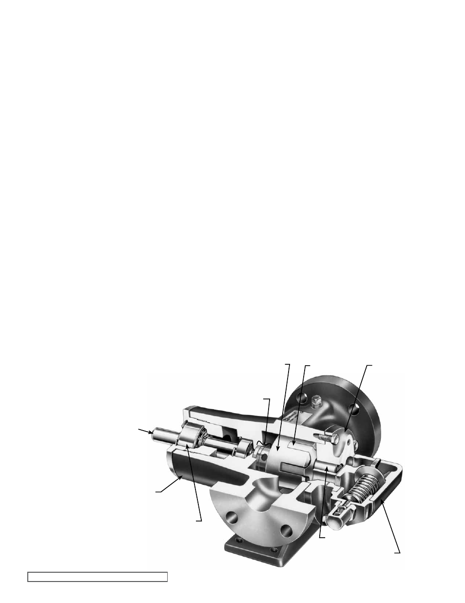
CUTAWAY Of MODELS gg, HJ OR HL4197
fIgURE 4
13. Disassemble the thrust bearing assembly.
gg, HJ, HL: Remove the outer snap ring from the
bearing housing and remove the ball
bearing. See
figure 9, page 7.
AS, AK, AL: Loosen the two setscrews in the flange
outside diameter. Rotate the end cap and
lip seal counterclockwise and remove.
Remove the ball bearing. See
figure 10,
page 7.
The casing should be examined for wear, particularly in the
area between the ports. All parts should be checked for wear
before the pump is put together.
When making major repairs, such as replacing a rotor
and shaft assembly; it is advisable to also install a new
mechanical seal, head and idler pin assembly, and idler and
bushing assembly. See
“Installation of Carbon graphite
Bushings,” page 8.
Clean all parts thoroughly and examine for wear or damage.
Check the lipseals, ball bearings, bushing and idler pin and
replace if necessary. Check all other parts for nicks, burrs,
excessive wear and replace if necessary.
In 2005, the use of single seal bearings were phased out.
Pumps now use “Sealed for Life” bearings that have seals
on both sides.
For older models, wash the bearings in clean solvent. Blow
out the bearings with compressed air. Do not allow the
bearings to spin; turn them slowly by hand. Spinning the
bearings will damage the race and balls. Make sure the
bearings are clean, then lubricate with non-detergent SAE
30 weight oil and check for roughness. Roughness can be
determined by turning the outer race by hand. Replace the
bearings if they have roughness.
Be sure the shaft is free from nicks, burrs and foreign
particles that might damage the mechanical seal. Scratches
on the shaft in the seal area will provide leakage paths under
the mechanical seal.
3. NOTE: The four valve capscrews, valve and gasket must
be removed from the GG4197 model before the six head
capscrews are removed.
Remove the head capscrews.
4. Tilt
the top of the head back when removing to prevent
the idler from falling off the idler pin. Avoid damaging the
head gasket.
Remove the head from the pump.
5. Remove the idler and bushing assembly. If the idler
bushing needs replacing, see
“Installation of Carbon
graphite Bushings,” page 8.
6. Insert a brass bar or piece of hardwood in the port
opening and between the rotor teeth to keep the shaft
from turning. Turn the locknut counterclockwise and
remove the locknut from the shaft. See
figure 9 or 10,
page 7.
7. Loosen the two setscrews in the face of the bearing
housing and turn the thrust bearing assembly
counterclockwise and remove from casing. See
figure
9 or 10, page 7.
8. gg, HJ, HL: Remove the snap ring from the shaft.
See
figure 9, page 7.
AS, AK, AL: Remove the bearing spacer from the shaft.
See
figure 10, page 7.
9. Remove
the brass bar or piece of hardwood from the
port opening.
10. The rotor and shaft assembly can now be removed by
tapping on the end of the shaft with a lead hammer or,
if using a regular hammer, use a piece of hardwood
between the shaft and hammer. The spring and rotary
member of the seal will come out with the rotor and shaft.
11. gg, HJ, HL: Remove the inner snap ring and single row
ball bearing from the casing.
See
figure 9, page 7.
AS, AK, AL: Remove the bearing retainer washer.
See
figure 10, page 7.
12. With a drift or screwdriver inserted in the shaft end of
the casing, tap the stationary seat from the casing. See
figure 11, page 7 and figure 13, page 8.
MECHANICAL SEAL
ROTOR
IDLER
HEAD
IDLER PIN
RELIEf VALVE
BALL BEARINgS
CASINg
SHAfT