Viking Pump TSM164: GG-AL 4197 User Manual
Page 7
SECTION TSM 164
ISSUE
F
PAGE 7 OF 10
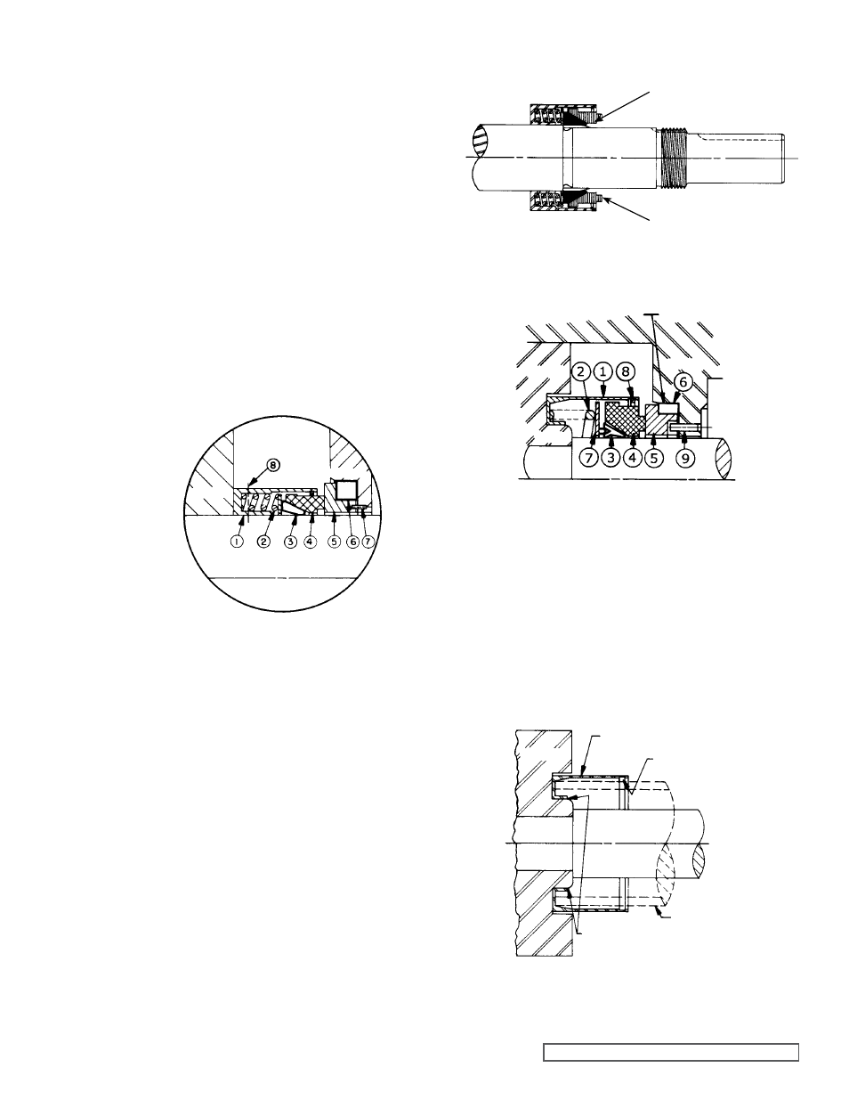
fIgURE 9
fIgURE 11
gg4197 SEAL RETAINER CARTRIDgE ON ROTOR HUB
fIgURE 12
Insert one inch pipe onto the retainer cartridge and press it
against the rotor hub, or, with a block of wood in each hand
push on the outside edge on the side to force the retainer
down the hub. It may be necessary to use a length of hard
wood and a light hammer to completely set the retainer
cartridge against the back of the rotor.
Check dimensionally from the end of the retainer to a
machined portion on the back of the rotor at least two places
180º apart. Runout should not exceed 0.003” (the plane
formed by the end of the retainer should be perpendicular to
the shaft as closely as possible).
Clean off the assembly just installed. Insert the spring and
disc. Lubricate the two piece PTFE wedge inside and outside
with SAE 30 oil. Place the tapered sleeve furnished with
the replacement seals on the shaft against the largest shaft
diameter and coat it with SAE 30 oil. Push the PTFE wedge
assembly over the tapered sleeve and using the carbon
washer, push the wedge onto the retainer against the disc.
Align the retainer with carbon washer indents, compress
and secure with retainer ring. When the carbon face is
compressed against spring, some “drag” should be felt, but
the spring must be able to push the wedge and carbon face
out against the retainer ring.
2. Remove the installation sleeve.
3. All models - Flush sealing faces of both the rotary
member and the seal seat with light oil and install the
rotor and shaft. Push the rotor and shaft into the casing
slowly until the ends of the rotor teeth are just below the
face of the casing.
Place the gasket on the head and install the head and
idler assembly on the pump. The pump head and casing
were marked before disassembly to ensure proper
reassembly. If not, be sure the idler pin, which is offset in
the pump head, is positioned toward and equal distance
between the port connections to allow for proper flow of
liquid through the pump.
COAT SHAfT AND TAPERED SLEEVE
WITH LIgHT OIL BEfORE ASSEMBLY
TAPERED SLEEVE
MECHANICAL SEAL
(ROTARY MEMBER)
fIgURE 10
MECHANICAL SEAL fOR
MODELS HJ, HL, AS, AK, AL4197
1. Retainer Cartridge
2. Springs
3. Wedge
4. Rotating Face (Washer)
5. Stationary Seat
6. Seat Ring (Gasket)
7. Anti-Rotation Pin
8. Drive Set Screws
SEAL SEAT BORE
ROTOR
CASINg
HUB
MECHANICAL SEAL fOR gg4197
1. Retainer Cartridge
2. Springs
3. Wedge
4. Rotating Face (Washer)
5. Stationary Seat
6. Seat Ring (Gasket)
7. Disc
8. Retaining Ring
9. Anti-Rotation Pin
ROTOR
SHAfT
INTERfERENCE
fIT
RETAINER CARTRIDgE
gROOVE fOR
RETAININg RINg
TUBULAR
INSTALLATION
TOOL
CASINg
SHAfT
ROTOR