Assembly – Viking Pump TSM143: N-P 335/4335 User Manual
Page 6
SECTION TSM
143
ISSUE
E
PAGE 6 OF 15
12. Clean all parts thoroughly and examine for wear and
damage. Check the idler bushing and idler pin; replace
if necessary.
If the idler pin is to be replaced, the oil groove must be
installed facing the center of the crescent on the head.
If lipseals need replacement, press into the end cap,
with the lip facing the bearings.
If the idler bushing is to be replaced, a press must be
used to remove the old bushing and install the new one.
The bushing position after being pressed in should be
flush with the face of the idler. For a carbon graphite
idler bushing, refer to
INSTAllATION Of CARbON
GRAPhITE bUShINGS, page 13.
Wash the anti-friction bearings (roller bearings) in clean
solvent. Blow out the bearings with compressed air. Do
not allow the bearings to spin; turn the bearing slowly by
hand. Spinning the bearings will damage the race and
rollers. Make sure the bearings are clean, then lubricate
with non-detergent SAE 30 weight oil and check for
roughness. Roughness can be determined by turning
the outer race by hand.
CAUTION: do not intermix the
inner and outer races for the roller bearings. Replace
the bearings if they have roughness.
Examine the casing for wear. Check the condition of
the casing at the sealing area (surface between suction
and discharge port). If the surface is in good condition,
the casing need not be replaced.
When making major repairs, such as replacement of a
rotor, it is usually considered advisable to install a new
head and idler. When making minor repairs, where only
an idler bushing and idler pin are required, other new
parts are usually not necessary.
the packing end of the rotor bearing sleeve. If the
bushing is carbon graphite, refer to
INSTAllATION Of
CARbON GRAPhITE bUShINGS, page 13.
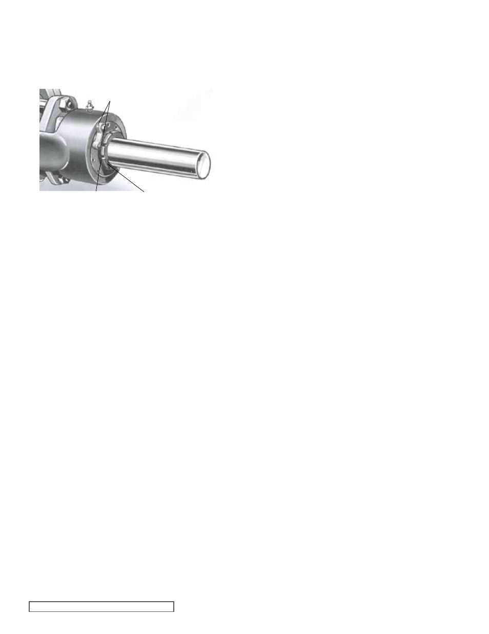
fIGURE 7
ASSEMbly
1. Install the rotor bearing sleeve and gasket on the casing.
Coat both sides of the gasket with thread sealant (pipe
dope) and quickly install the gasket and rotor bearing
sleeve on the casing. Place a support under the
rotor bearing sleeve to prevent the casing and rotor
bearing sleeve from tilting down while the rotor is being
installed.
2. Check the casing to be sure the drain plug has been
removed.
3. Carefully check the shaft, remove any burrs or rough
surfaces to avoid damaging the rotor bearing sleeve
bushing while installing the rotor and shaft into the
casing. Coat the inner diameter of the rotor bearing
sleeve bushing and shaft with a thin coat of non-
detergent SAE 30 weight oil.
Support the weight of the rotor with a hoist. A cable sling
can be used around the shaft, or rotor teeth to carry
the weight of the part while being assembled into the
casing.
Place the end of the rotor shaft through the casing,
into the bushing slowly turn rotor from right to left while
pushing into the casing. When the shaft first protrudes
from stuffing box, stop pushing. Check to see if the large
diameter of the shaft has protruded far enough into rotor
bearing sleeve to permit installing packing rings.
Use packing suitable for the liquid being pumped.
Lubricate packing rings with oil, grease or graphite to aid
assembly. Packing ring joints should be staggered from
one side of shaft to the other. A length of pipe will help
set each packing ring.
4. Place the packing gland and inner end cap (position
spanner wrench holes on side next to packing gland)
with lip seal (lip facing away from packing gland) over
the end of the shaft.
5. Push the rotor as far into the casing as it will go.
6. Prior to installing the head, coat the casing face with
thread sealant (pipe dope) and place a new .015” head
gasket on the mounting studs. Coat the dry side of
gasket with thread sealant (pipe dope) Place the idler
assembly on the idler pin and prepare to mount the head
and idler assembly. (
CAUTION! do not drop the idler on
the foot)
The pump head and casing were marked before
disassembly to ensure proper reassembly. If not, be
sure the idler pin, which is offset in the pump head, is
positioned toward, and equal distance between, the port
connections to allow for proper flow of liquid through the
pump. Place the head on the pump, slightly tilting the
top of the head back away from casing until the crescent
enters the inside diameter of rotor. Rotate the idler on
idler pin until the idler teeth mesh with the rotor teeth.
Raise the head until the face of the head is parallel with
face of the casing and work into position. Care must be
taken to avoid damaging the head gasket. Fasten to the
head to casing with nuts and tighten evenly.
LOCKWASHER WITH TANG
LOCKNUT
ADJUSTING NUT LOCK WITH
SELF-LOCKING PIN