Assembly – Viking Pump TSM143: N-P 335/4335 User Manual
Page 10
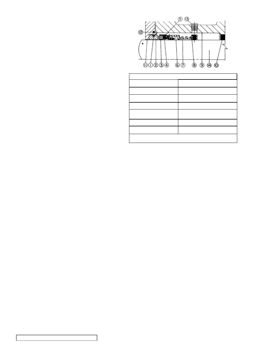
lIST Of PARTS
1. O-Ring Seat Gasket
8. Set Collar with set screws
2. Stationary Seat
9. Rotor Bearing Sleeve
3. Rotating Face (Washer) 10. Rotor Bearing Sleeve Bushing
4. Bellows
11. Seal Holder Plate
5. Metal Parts
(retainer, drive band)
12. O-Ring Gasket for seal holder
plate
6. Spring Adapter
13. Pipe Plug
7. Spring
14. Shaft
NOTE: Items one through seven comprise the complete mechanical seal
SECTION TSM
143
ISSUE
E
PAGE 10 OF 15
ASSEMbly
Standard Mechanical Seal (Synthetic Rubber Bellows Type)
Prepare all parts for reassembly ahead of time. Pack roller
bearings with multi-purpose grease, NLGI # 2 and have all
new gaskets on hand.
Be especially careful to keep mechanical seal parts clean.
Minute dirt particles especially on the seal faces, will cause
leakage. Never touch the seal faces with anything except
clean hands or a clean cloth.
Once the rotating portion of mechanical seal is installed on
rotor shaft, it is necessary to assemble parts as quickly as
possible to ensure the seal does not stick to the shaft in the
wrong axial position. The seal should be expected to stick to
the shaft after several minutes setting time.
1. Deburr the threads on the rotor shaft with a fine file and
place a layer of tape over the threads to protect the rotor
bearing sleeve bushing during assembly. Gently radius
leading edge of the largest diameter on the shaft (.03
inch is sufficient to aid in seal installation). Smooth the
radius with a very fine grit emery cloth. Polish the rotor
shaft from leading edge through mechanical seal area
with the emery cloth. Any scratches left on shaft in seal
area will provide leakage paths under mechanical seal.
2. Install the rotor bearing sleeve and gasket on the casing.
Coat both sides of the gasket with thread sealant (pipe
locks and with a spanner wrench, remove the end caps.
Examine the lipseal and replace if worn.
Remove the roller bearings.
10. Remove the nuts and capscrews and take off the thrust
bearing housing.
11. Remove the nuts holding the seal plate and remove seal
plate. The stationary seal seat can be removed from the
seal plate and the rotating portion of the seal from the
rotor bearing sleeve, remove the spring and set collar
from the bottom of the seal chamber.
12. Check rotor the bearing sleeve bushing while the rotor
bearing sleeve is mounted on the casing. If worn, the
bushing must be replaced.
Disconnect the flush line and remove the rotor bearing
sleeve from the casing.
A press must be used to remove the old bushing. If
the bushing has a shoulder on the stuffing box end,
it must be pressed out from the mechanical seal end
of the rotor bearing sleeve. Carbon graphite bushings
are standard for Model 4335 pumps. To replace carbon
graphite bushings, refer to
INSTAllATION CARbON
GRAPhITE bUShINGS, page 12.
13. Clean all parts thoroughly and examine for wear and
damage. If lipseal replacement is needed, press in the
end cap with the lip facing the end of the shaft. Check
the idler bushing and idler pin, replace if necessary.
If the idler pin is to be replaced, the oil groove on the
pin must be installed facing the center of the crescent
on the head.
If the idler bushing is to be replaced, a press must
be used to remove the old bushing and install new.
The bushing position after being pressed in should
be flush with teh face of the idler. For carbon graphite
idler bushing, refer to
INSTAllATION Of CARbON
GRAPhITE bUShINGS, page 12.
14. Wash the bearing in clean solvent. Blow out bearings
with compressed air. Do not allow the bearings to spin;
turn the bearing slowly by hand. Spinning the bearings
will damage the race and rollers. Make sure the
bearings are clean, then lubricate with non-detergent
SAE 30 weight oil and check for roughness. Roughness
can be determined by turning the outer race by hand.
CAUTION: do not intermix the inner and outer races for
the roller bearings.
15. Examine the casing for wear. Check the condition of
the casing at the seal area (surface between suction
and discharge ports). If the surface is in good condition,
the casing need not be replaced. When making major
repairs, such as replacement of a rotor, it is usually
considered advisable to install a new head and idler.
When making minor repairs, when only an idler bushing
and idler pin are required, other new parts are usually
not necessary.
16. Inspect the mechanical seal for wear or damage.
Refer to Figure 14 for mechanical seal list of parts. In
general, if the pump has been operated long enough
to exhibit other worn parts, it is likely the seal will have
fIGURE 14 MEChANICAl SEAl
to be replaced. Replacing individual seal parts is not
recommended, i.e., a used seal washer will not perform
satisfactorily when run against a new stationary seat.