Unitec ReachFree ID for C-Start User Manual
Page 22
R E A C H F R E E I D
Document Number:
RFID1001
18
Document Name:
Unitec RFID Field Retrofit Installation Guide
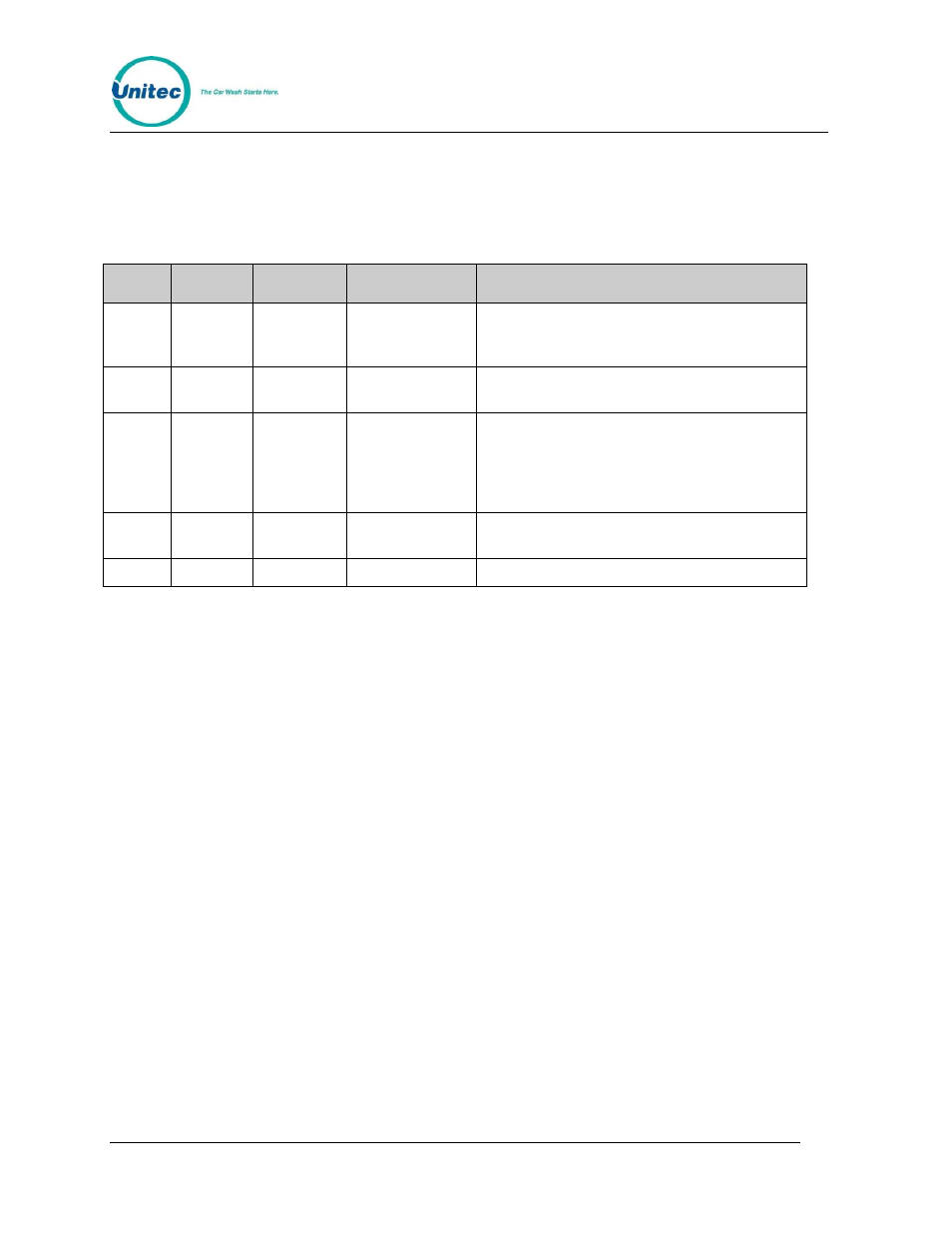
LEDS
The RFID board has 5 LEDs that indicate whether or not the RFID system is working. The table
below defines each LED and its function.
LED
Label
Color
Light Status
Description
LED 1
Serial
Red
Blinks during
data transfer
Indicates when the RF Reader sends data to
the RFID board. Most of the time this will be
when the RF Reader senses a RF tag.
LED 2
I2C
Yellow
Blinks during
data transfer
Indicates when the RFID board sends and
receives data to and from the entry unit
LED 3
Ant On
Green
Solid
Indicates when the reader is enabled. If the
reader is enabled by the proximity sensor, then
this LED will be OFF most of the time. If the
reader is always enabled then this LED will be
constantly lit.
LED 4
Status
Green
Blinking
Blinks once per second to show that the RFID
board is alive
LED 5
Power
Green
Solid
Indicates power to the board
Tips and Suggestions
The ReachFree ID reader uses the 900 MHz frequency which can cause interference with
other electronic devices that use the 900 MHz frequency range. Unitec strongly suggests you
observe the following warnings:
Stay away from UHF communications devices.
Avoid arc lighting fixtures by 3 or 4 feet.
Keep neighboring long-range readers on parallel lanes at least 12 feet apart, with
their surveillance zones parallel to each other.
Do not have identical readers facing each other (but “back-to-back” is OK).