Anti-spatter sprayer, 01 starting installation, 02 wiring the qrm-3 anti-spatter sprayer – Tweco QRM-3 Anti-Spatter Sprayer User Manual
Page 9
anti-spatter sprayer
2-5
SM-QRM-3
inStAllAtion And opeRAtion
10
1
5
8
2
6
7
11
3
4
9
SECTION 3:
INSTALLATION AND OPERATION
3.01 Starting Installation
The QRM-3 Anti-Spatter Sprayer was primarily designed
to be mounted at the right side of the Tweco
®
Robotics
QRC
TM
-2000 Nozzle Cleaning Station. It can also be
mounted in a variety of other convenient locations. For
best results, the sprayer should be installed within the weld
cell at a convenient location where the welding torch can
easily access. The QRC
TM
-2000 Nozzle Cleaning Station
has all the necessary mounting holes needed to install the
QRM-3 anti-spatter sprayer.
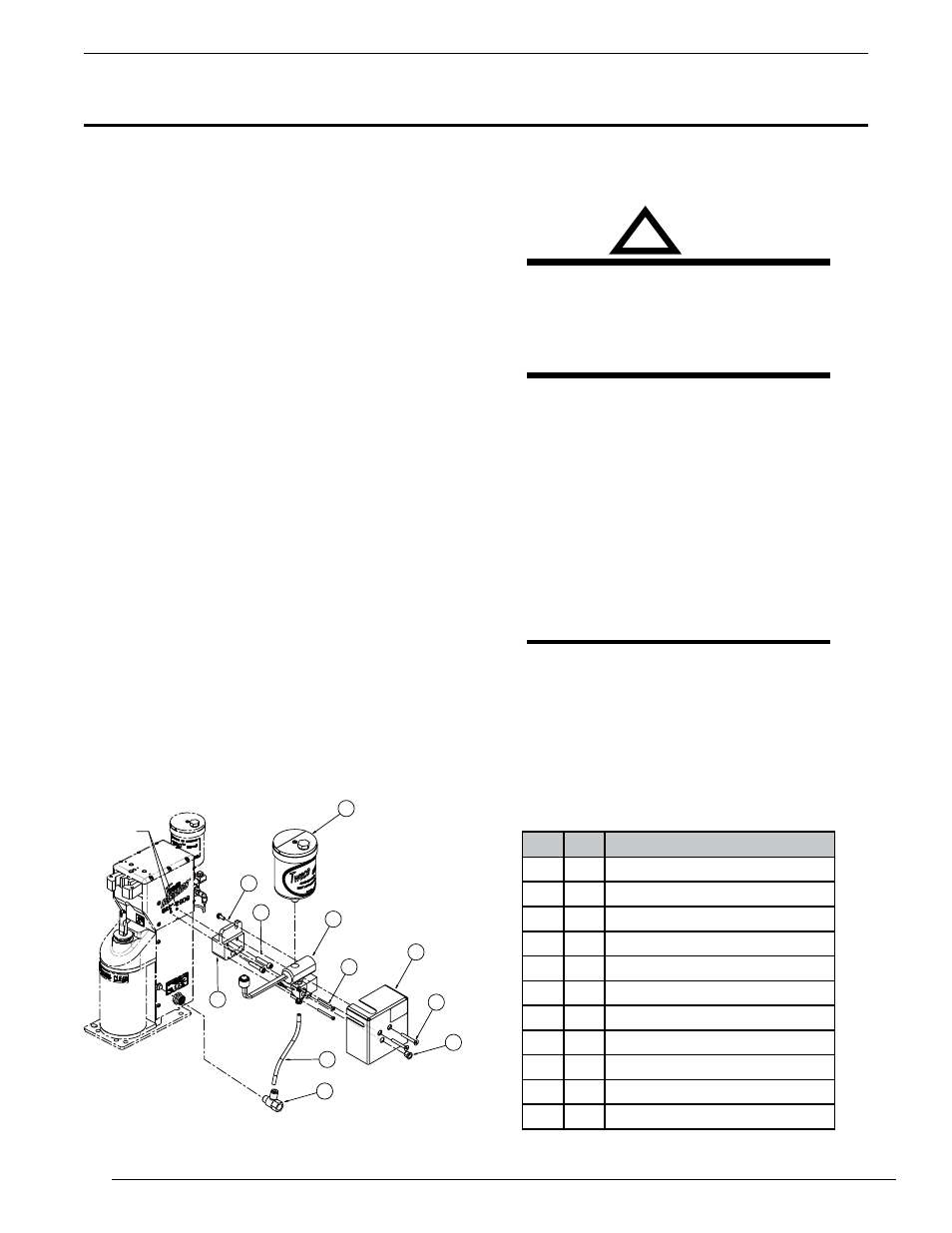
1. Attach the mounting block (#5) to the right side of the
QRC-2000 using two (2) 1/4-20 x 1.25” screws (#1)
(use Loctite).
2. Assemble the mister/valve sub-assembly (#8) onto
the mounting block with two (2) No.6-32x1.5” screws
(#7) (use Loctite).
3. Install 10-32 x1/2 screw (#10) with lock washer into
mister/valve sub assembly.
4. Screw the air fitting (#4) into the air intake port on the
QRC
TM
-2000.
5. Press one end of the 1/4” tubing (#9) into the air
fitting (#4) and the other end in to the bottom of the
sprayer/valve sub-assembly (#8).
6. Remove the red plug in the side of the sprayer/valve
sub-assembly. Place the cover (#6) over the sub-
assembly as shown and screw the exhaust port (#3)
into the hole on the side of the cover. Attach the cover
with (2) 10-32 x 11⁄2” counter-sunk screws. (#11).
No. Qty.
Description
1
2
1/4-20 X 1.25” SHCS
2
1
Reservoir
3
1
1/8-27 NPT Exhaust
4
1
Male-Female Tee Fitting
5
1
Mounting Block
6
1
Cover
7
2
6-32 X 1⁄2” Machine Screw
8
1
Sprayer/Valve Sub-Assembly
9
1
1/4” Poly Tubing 7” Long
10
1
10-32 X 1/2 HH w/ Lock Washer
11
2
10-32 X 1-1⁄2” C-Sunk Screw
Figure 2
3.02 Wiring the QRM-3 Anti-spatter
Sprayer
!
WARNING
Shut off poWeR befoRe connecting the WiReS
to the QRc-2000 ciRcuit boARd. do not SWitch
ciRcuit boARd SouRcing And Sinking SWitcheS
With poWeR on. dAMAge Will occuR. only Move
SWitcheS When the poWeR iS off.
Remove the shroud from the back of the QRC
TM
-2000
Nozzle cleaning station. Run the wires from the sprayer/
valve sub-assembly into shrouded area through a small
groove just under the mounting block. Measure the wires
to the circuit board, leaving an extra 2-3 in., and cut the
wires. Wire the QRM-3 as shown in the wiring diagram.
Replace the shroud back on to the unit with the wire placed
in the groove below the mounting block.
The drawings in Figure 3 show the QRM-3 wiring
connections.
NOTE
The color of QRM-3 leads does not make a
difference to which pins they go.
mounting
holes