Installation/setup transmig 2rt – Tweco 2RT Transmig User Manual
Page 19
INSTALLATION/SETUP
TRANSMIG 2RT
Manual 0-5196
3-3 INSTALLATION/SETUP
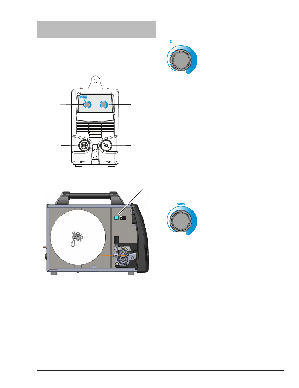
3.06 2RT Wire Feeder Controls,
Indicators and Features
The 2RT Wirefeeder is designed to be used with the
Transmig 250i. Select MIG Process and REMT in the
Advanced Features menu on the Transmig 250i to enable
the controls on the 2RT wirefeeder. See the 250i Operat-
ing manual for details.
Volts
Wirespeed
Left Knob
Right Knob
1
2
3
4
Art # A-10404
Figure 3-1: 2RT Front Panel Controls
Art # A-10470_AB
5
REMOTE
LOCAL
Figure 3-2: 2RT Local/Remote Switch
The Tweco professional MIG Torch will connect to the 2RT
just as it does to the 250i power source. The electrode
Polarity setting is done at the power source. See sub
sections 3.09 and 3.10.
1. Left Knob: WFS (Wire Feed Speed) Control
Amperage Control
Wirespeed
Left Knob
The Left Knob controls the Wirespeed in the wirefeeder.
It adjusts the preview wire speed display in the power
source. The amperage control knob adjusts the amount
of welding current delivered by the power source. In MIG
mode, the amperage knob adjusts the speed of the wire
feed motor (which in turn adjusts the output current by
varying the amount of MIG wire delivered to the welding
arc). The optimum wire speed required is dependent on
the type of welding application. The setup chart on the
inside of the wire feed compartment door of the Transmig
250i provides a brief summary of the required output set-
tings for a basic range of MIG welding applications. The
value may also be adjusted while a weld is in progress – if
this occurs, the left display will briefly switch to show the
adjusted value as the knob on the 2RT is turned, and will
automatically revert back to showing the set weld current
measurements when the knob is not being turned.
2. Right Knob: MIG Voltage Control
Right Knob
MIG Voltage Control
In this mode the control knob is used to adjust the output
voltage of the power source. It adjusts the preview volt-
age display in the power source. The welding voltage is
increased by turning the knob on the 2RT clockwise or
decreased by turning the knob anti-clockwise. The opti-
mum voltage level required is dependent on the type of
welding application. The setup chart on the inside of the
wire feed compartment door of the power supply provides
a brief summary of the required output settings for a basic
range of MIG welding applications. The value may also
be adjusted while a weld is in progress – if this occurs,
the left display on the power supply will briefly switch to
show the adjusted value as the knob on the 2RT is turned,
and will automatically revert back to showing the set weld
current measurements when the knob is not being turned.