Torch leads replacement, Torch leads replacement -2 – Tweco PWH-M 2A User Manual
Page 24
Service
4-2
Manual 0-2005
2) Turn the torch upside down and slide the gas
distributor (3), (end with holes in last), into the
torch.
CAUTION
Care must be taken to insure that the gas dis-
tributor (3) is installed in the correct direction.
3) Screw the electrode cap (9) on firmly then back
off a couple of turns so that the electrode (8)
can be adjusted.
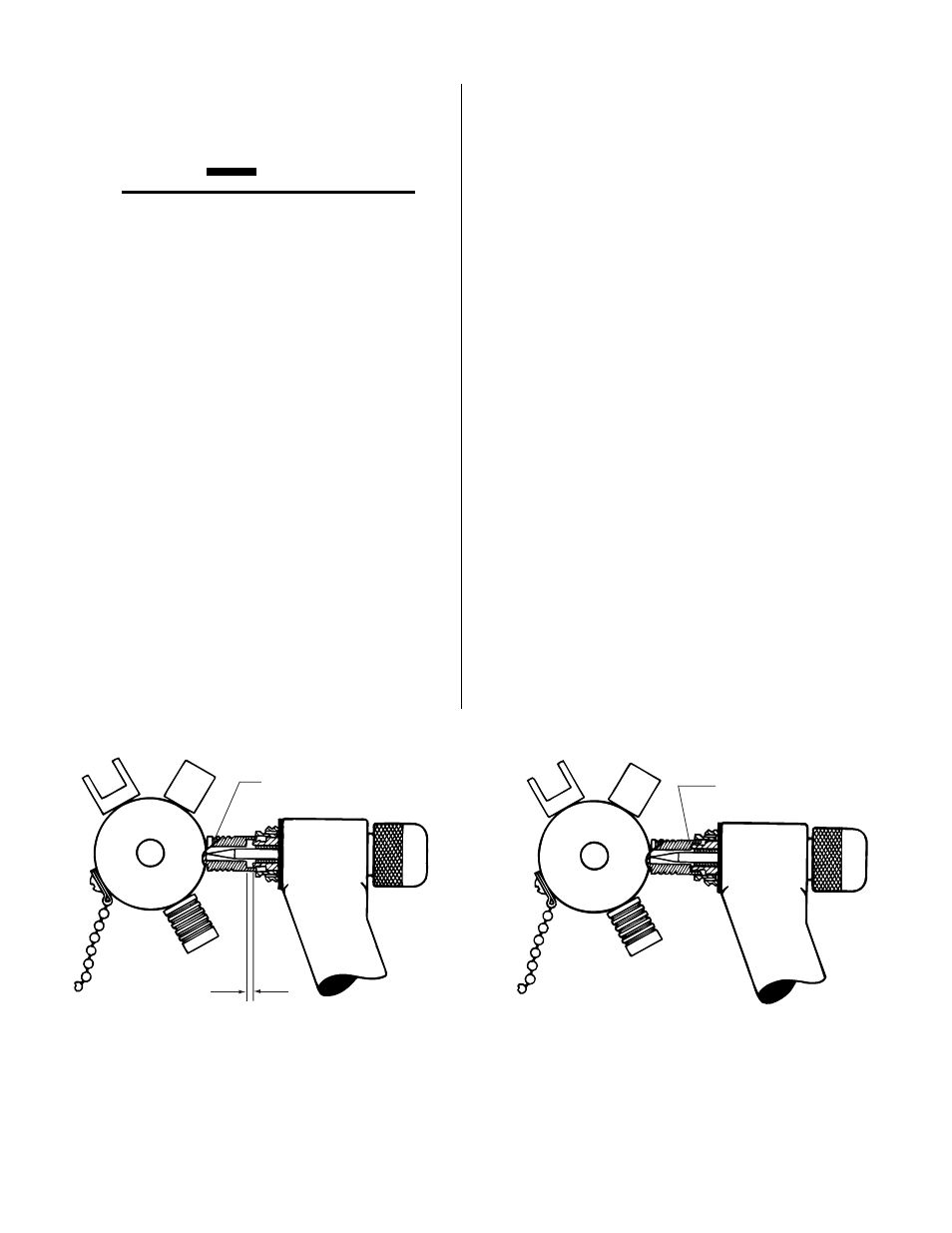
4) Select the proper gauge on the gauge and
wrench (10) assembly. The electrode (8) must
contact the gauge to be properly adjusted (Fig.
4-B). Insert the gauge into the front of the torch
and press until the shoulder of the gauge con-
tacts the torch anode (Step 2, Fig. 4-B). Tighten
the electrode cap (9) securely while holding
pressure against the gauge.
5) Install the welding tip (2) and tighten gently
with the tip wrench (10).
6) Stretch the gasket (4) over the front end of the
torch and position against the torch body.
7) Screw on shield cup (1).
The torch is now assembled and ready to be checked
for possible leakage before operating. Turn on the torch
coolant recirculator and observe the tip and orifice of
the torch for possible sign of moisture.
Turn on the plasma gas and watch the gas stream for
possible signs of moisture in the stream before operat-
ing. Do not attempt to operate the torch until the source
of the moisture has been identified and corrected.
4.2. TORCH LEADS
REPLACEMENT
Hand Torch
1) Cut off the shrink-on tubing that is at the end of
the handle and leads sleeving.
2) Unscrew the handle from the torch.
3) Disconnect the four hoses from the torch.
4) Remove the handle from the old leads and in-
sert on new leads.
5) Connect the new leads to the torch making sure
the color coded leads mate with their color
coded torch fittings. Do not over-tighten.
6) Screw the handle back onto the torch.
7) Slide the new shrink-on tubing over the handle
until 1/2 of it is on the handle. Shrink the tub-
ing with heat (not flame) until it is firm around
the handle and sleeving.
Figure 4-B Gaging Electrode
Gauge ring ident.
Initial gap
Gauge seated
Step 1
Step 2