09 operation hours display, 10 protection and safety circuits, Portafeed vs 212 – Tweco VS 212 PortaFeed User Manual
Page 37: 08 meter hold function
PORTAFEED VS 212
Manual No. 0-4994
4-5
OPERATION
3. Using Table 4-1 as a reference, carefully slide each white DIP switch left or right to change the meter to the
desired function.
DIP Switch #
1
2
3
4
LEFT Position
Hold Function "Off" Wire Feed Speed Displayed Wire Feed Speed in IPM
Currently Not In Use
RIGHT Position
Hold Function "On"
(refer to 4.07)
Output Current Displayed
Wire Feed Speed in MPM Currently Not In Use
Table 4-1: Lower Meter Switch Settings
4.10 Protection And Safety
Circuits
The following protection and safety circuits come
standard with this wire feeder and are designed to
protect (by disabling the wire feeder) against
unfavorable operation and/or equipment damage.
1. Undervoltage Protection: If the input voltage
drops below the specified voltage range for an
extended period of time, an electronic circuit will
activate, and the wire feeder will not operate. The
undervoltage protection circuit will automatically
deactivate when the input voltage enters an
acceptable range.
2. Overvoltage Protection: If the input voltage rises
above the specified voltage range for an extended
period of time, an electronic circuit will activate,
and the wire feeder will not operate. The
overvoltage protection circuit will automatically
deactivate when the input voltage enters an
acceptable range.
3. Input Current Protection: If the input current rises
above the specified maximum input current for
an extended period of time, the input circuit
4.08 Meter Hold Function
The meter hold function is enabled when DIP switch
number 1 is set to the "RIGHT" position as defined in
the table above. When this function is activated, the
meter's displays are retained for 5 seconds after the
last welding operation has ended. This provides the
time needed for the operator to remove his welding
shield and read the meters before the display goes
blank.
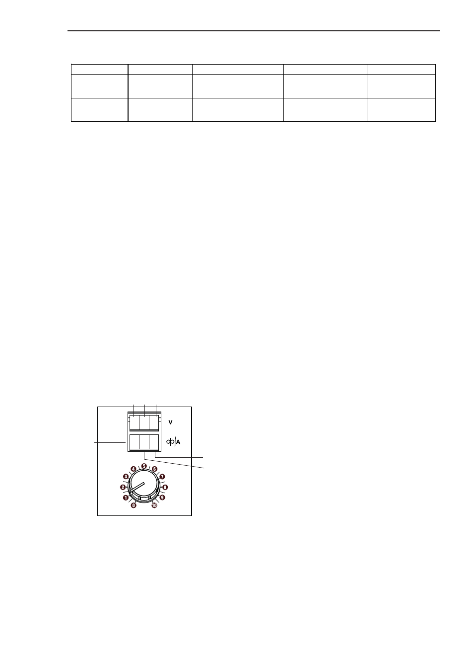
4.09 Operation Hours Display
The total number of arc hours that the VS 212 has
been operating can be displayed by pressing and
holding the small black button located directly above
the 4 DIP switches shown in Figure 4-7. The reading
is displayed over both meters as follows:
Art # A-07258
Tho
us
an
ds
Hun
dr
ed
s
Te
ns
Ones
Hundreths
Tenths
1 2 3
4.5 6
Figure 4-8: Displaying Operation Hours
For example, the above display would be read as:
1,234.56 hours