09 internal controls and connections, 09 internal controls and connections -7, Portafeed vs 212 – Tweco VS 212 PortaFeed User Manual
Page 25
PORTAFEED VS 212
Manual No. 0-4994
2-7
INTRODUCTION
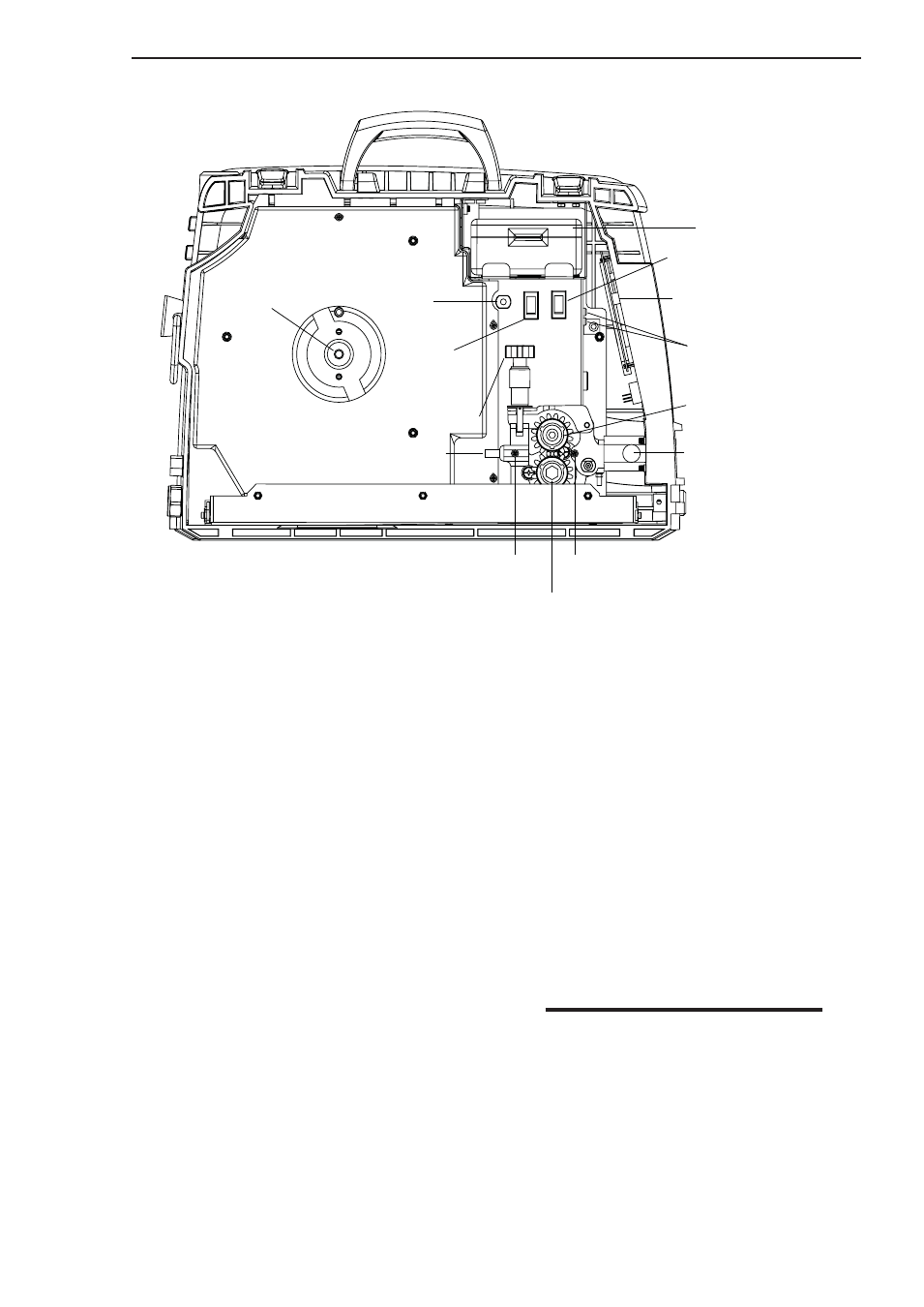
2.09 Internal Controls And Connections
1. STORAGE BOX: On the job storage for drive rolls,
tips, nozzels, etc. To remove, lift up to release
velcro and slide it up and over the side retainers.
2. HIGH/LOW RANGE SWITCH: Gives a finer dial
control over the wire speed, which is especially
useful with larger diameter flux-cored wires.
3. WIRE SPEED/AMP METER SELECTION DIP
SWITCHES: Set these switches to change the lower
meter display from wire speed to amperage output
of the power source. Refer to Section 2.08, item 3
and section 4.07 for DIP switch setting information.
4. CARTRIDGE GUN LEADS: These two spade
terminals provide the MIG gun switch connection.
5. UPPER RETAINING KNOB: This knob is used to
secure the bearing feed roll. Remove this knob to
change the bearing feed roll.
6. GUN CLAMP KNOB: Tighten this knob to secure
the welding gun to the wire feeder.
7. OUTPUT GUIDE LOCKSCREW: Tighten this screw
to secure the output wire guide.
8. LOWER RETAINING KNOB: This knob is used to
secure the drive feed roll. Remove this knob to
change the drive feed roll.
9. INPUT GUIDE LOCKSCREW: Tighten this screw
to secure the input wire guide.
10.INPUT WIRE GUIDE: This guide is required to
direct the welding wire from the wire spool to the
drive feed roll.
11.SPRING TENSION KNOB: Use the spring tension
knob to adjust the amount of force the bearing
feed roll exerts on the welding wire.
12.CC/CV MODE SWITCH: The CC position provides
a voltage sensing wire feed speed mode of
operation for use with constant current (CC) power
sources. The CV position provides a constant wire
feed speed mode of operation for use with constant
voltage (CV) power sources.
NOTE
This switch does not select a CC or CV mode
of operation. The mode of operation is set
by the type of power source being used.
13.INPUT CIRCUIT BREAKER: This circuit breaker
provides complete system protection for the wire
feeder in the case of a fault or overload condition.
14.HUB TENSION BOLT: The hub tension bolt is used
to adjust the wire spool tension which acts as a
mechanical brake to assist in the stopping of the
welding wire at the completion of a weld.
(14) HUB TENSION
BOLT
(13) INPUT CIRCUIT
BREAKER
(12) CC/CV MODE
SWITCH
(2) HIGH/LOW RANGE SWITCH
(11) PRESSURE ADJUST DEVICE
(5) UPPER RETAINING KNOB
(7) OUTPUT GUIDE LOCKSCREW
(6) GUN CLAMP KNOB
(8) LOWER RETAINING KNOB
(9) INPUT GUIDE LOCKSCREW
(10) INPUT WIRE GUIDE
Art # A-07138
(1) STORAGE BOX
(3) WIRE SPEED/AMP METER
SELECTION DIP SWITCHES
(4) CARTRIDGE GUN LEADS
High
Low
CC
CV
Figure 2-4: Internal Controls and Connections.