Tweco 200 Ultra-Cut User Manual
Page 46
Manual No. 0-5056 Ultra-Cut 200
3-22
INSTALLATION
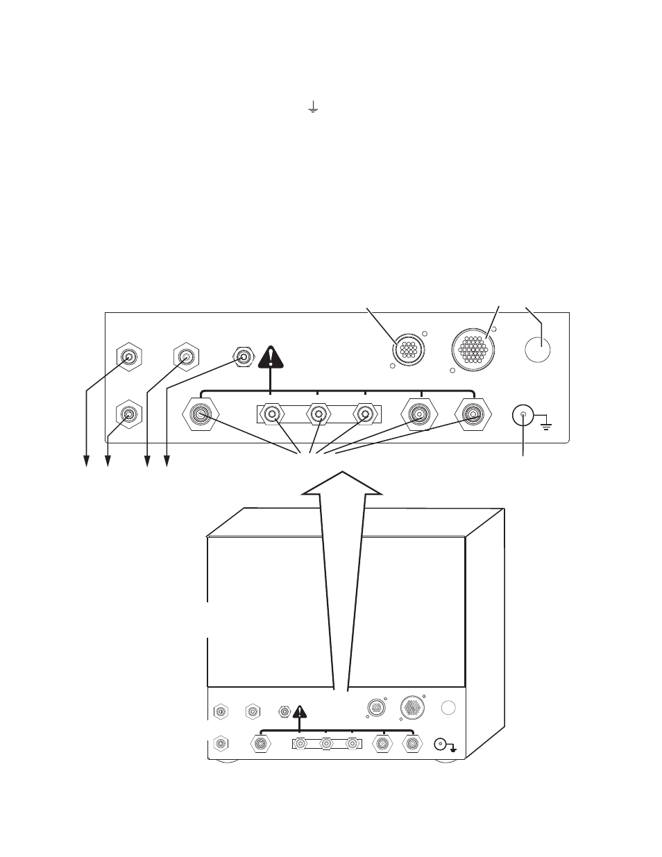
3.15 Gas Control Module: Control, Input, and Output Connections
1. Make all other connections to the rear of the Module. The connections are labeled. The Module must be
grounded; the grounding terminal is marked Use #10 AWG (European 6 mm
2
) (or thicker) wire for
grounding. Keep the ground wire as short as possible.
2. Position the Module on a flat, horizontal, mounting surface.
3. Ensure that the Flowmeters are plumb.
4. Secure the Module to the mounting surface.
5. Connect all gas / water inputs to the rear panel of the module.
6. Connect the appropriate control cables to terminals marked ‘TVA’ (torch valve assembly) and ‘power sup-
ply’.
Gas & Water Inputs (Check Valves)
Connection Panel
To Torch Valve Assembly
To Torch Valve Assembly
To Power Supply
SHIELD
PLASMA
PREFLOW
H O
SHIELD
2
H O
2
AIR
N2
O2
H35
F5
TVA
POWER
SUPPLY
COMM
J57
J56
INPUTS
When Cutting With O2 Plasma
Air MUST BE Connected
Ground Stud
SHIELD
PLASMA
PREFLOW
H O
SHIELD
2
H O
2
AIR
N2
O2
H35
F5
TVA
POWER
SUPPLY
COMM
J57
J56
INPUTS
When Cutting With O2 Plasma
Air MUST BE Connected
Gas Control Box
Rear Panel
Art # A-06881