Tweco PakMaster 75XL Plus (CE) User Manual
Page 22
INSTALLATION
3-6
Manual 0-2782
8.
Remove the top nut and washer from the Pilot
Stud.
9.
Place the lug on the Pilot Control Wire onto the
stud and secure with the nut and washer removed
in the above Step.
10. Tighten the Strain Relief onto the Torch Leads.
11. Check the torch for proper parts assembly.
12. Close the access panel and turn the latching screw.
B. Machine Systems (PCM-62 Torch with
Unshielded Leads)
WARNING
Disconnect primary power at the source before as-
sembling or disassembling the power supply, torch
parts, or torch and leads assemblies.
1.
Turn the screw latch securing the front access panel
to the power supply front panel.
2.
Lift the access panel to gain access to the torch
bulkhead panel.
3.
Remove the retaining nut from the Strain Relief.
Strain Relief
Nut
Strain Relief
Torch Leads
Assembly
A-02827
Figure 3-7 Strain Relief Nut Removal
4.
The Adapter supplied with the Power Supply must
be installed per the following:
a. Inside the Power Supply Bulkhead area, route
the connector on the free end of the Adapter
through the Strain Relief Nut.
b. Continue routing the connector out the hole in
the front panel of the Power Supply.
c. Feed the end of the torch lead and the Strain
Relief into the hole in the unit while routing
the single black wire into the notch of the Strain
Relief.
d. Tighten the Strain Relief Nut to secure the
Strain Relief to the Power Supply.
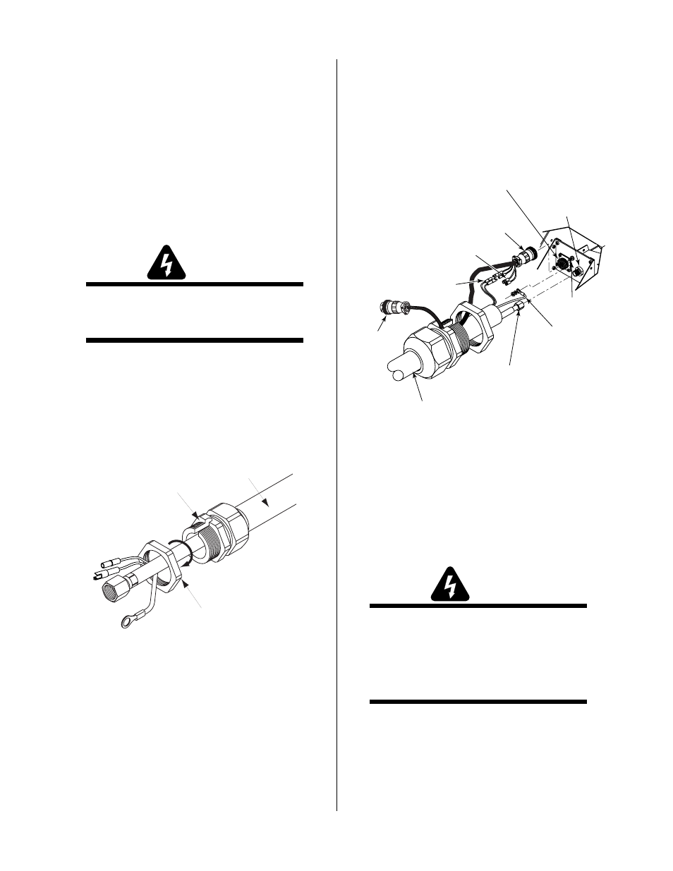
Adapter
(Supplied With
Power Supply)
Pilot Lead
Torch Lead
Assembly
Negative/Plasma
Lead
Adapter Connector
Pilot Lead
Stud
Negative/Plasma
Lead Connection
A-02828
Control (PIP) Circuit
Connectors
Shield Connectors
(Not Used)
Remote
Cable
Connector
Figure 3-8 Torch Lead Connections
5.
Connect the torch Negative/Plasma Lead to the
bulkhead connection inside the Power Supply.
6.
Connect the Control (PIP) Circuit Connectors to
the mating connectors on the Adapter supplied on
the Power Supply (see Warning).
WARNING
The Adapter supplied with the Power Supply has
two additional Shield Connectors that are used for
Shielded Systems only. These two connectors are
not used and need to be taped out of the way to
prevent contacting the Negative/Plasma or Pilot
Leads.
7.
Remove the top nut and washer from the Pilot
Stud.
8.
Place the lug on the Pilot Control Wire onto the
stud and secure with the nut and washer removed
in the above Step.
9.
Tighten the Strain Relief onto the Torch Leads.