Tweco GCM-6000 Gas Control User Manual
Page 22
INSTALLATION PROCEDURES
16
Manual 0-2641
If the Gas Control Module serial number ends with
the letter 'B' or earlier install additional parts per
the following:
a. Locate the short wiring harness and inline splice
supplied with the option.
b. Inside the Gas Control Module locate E26 in
the lower right hand corner (viewed from the
rear of the unit) of the PC Board.
c. Place the inline splice over the wire connected
to E26.
Wire From Option
Wire Harness (Short)
Existing Wire
(From GCM Harness
at PC Board E26)
Crimp Closed
A-02383
Figure 3-12 Inline Splice Installation,
d. Place the free end of the single wire #24 from
the short wiring harness into the other slot of
the inline splice.
e. Close the inline splice making sure that it snaps
closed.
Mating Plug From
GCM Wiring Harness
Connector From
Option Wiring Harness
A-02377
Figure 3-13 Wiring Harness Connections
f. Remove the two nuts from the ground stud at
the rear of the Gas Control Module.
g. Pull the groud stud out of the panel and place
the wire with the ring terminal over the stud.
Insert the stud back into the panel hole and
secure with the two nuts removed above.
h. Connect wire #110 with piggy-back faston to
one of the tabs on the the Water Solenoid Valve.
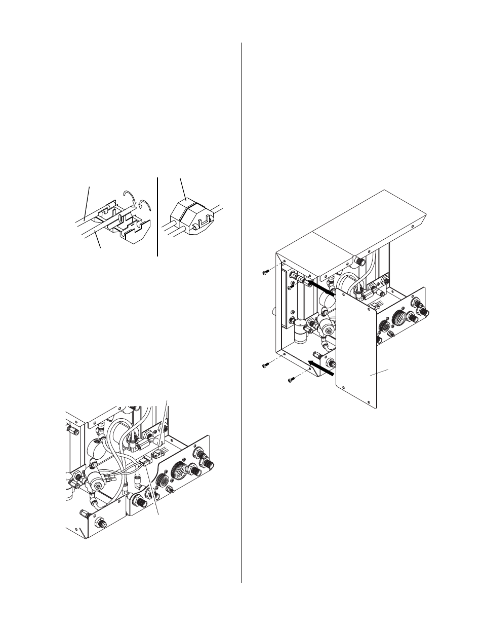
11. Install the Right Side Panel from the Gas Control
Module to the right side of the Optional Second-
ary Gas/Water Flow Control Module.
Screws
(4 Places)
Right Side
Panel
A-02378
Figure 3-14 Right Side Panel Installation
12. Reinstall the Left Side Panel and then the Rear
Panel to the Gas Control Module.
13. Reinstall the Rear Panel to the Optional Second-
ary Gas/Water Flow Control Module.