Tweco GCM-6000 Gas Control User Manual
Page 21
Manual 0-2641
15
INSTALLATION PROCEDURES
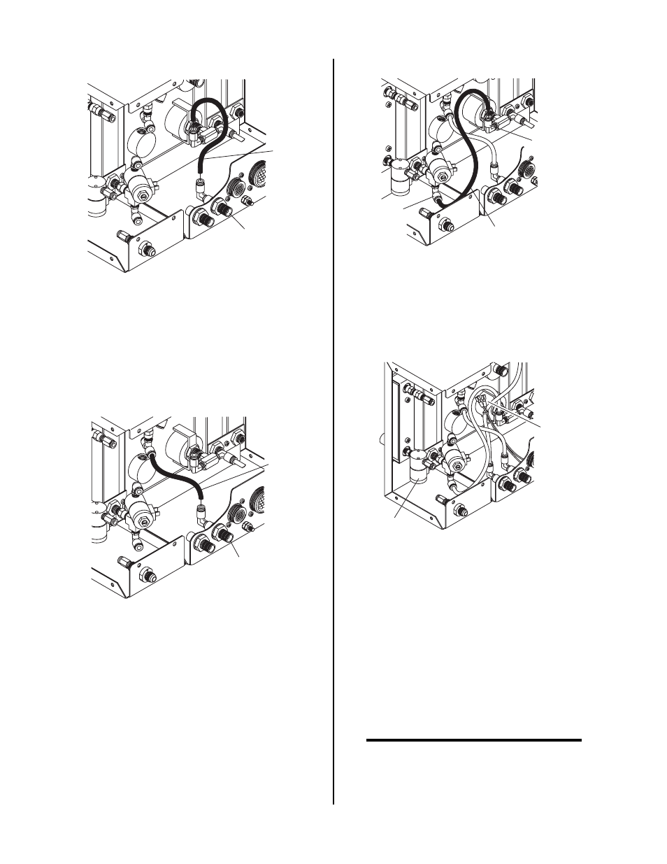
Hose
SECONDARY
Output Fitting
A-02373
Figure 3-8 Secondary Gas Hose Removal
6. Locate the free end of the hose connected to the tee
on the output side (top) of the gas flowmeter in
the Optional Secondary Gas/Water Flow Control
Module. Connect this end to the SECONDARY
output fitting inside the Gas Contol Module.
SECONDARY
Output Fitting
Hose
A-02374
Figure 3-9 Connecting Secondary Gas Ouptut Hose
7. Locate the free end of the hose connected to the
input (bottom) of the gas flowmeter in the Optional
Secondary Gas/Water Flow Control Module. Con-
nect this end to the output fitting at the gauge as-
sembly inside the Gas Control Module.
Hose
Input To
Flowmeter
Output
From Gauge
Assembly
A-02375
Figure 3-10 Connecting Gas Flowmeter Input Hose
8. Inside the Gas Control Module remove the tie wrap
holding the two wires, with insulated faston ter-
minals, to the hose.
Wires With
Fastons
Water Solenoid
Valve
A-02376
Figure 3-11 Secondary Water Solenoid Wire
Connections
9. Connect the two wires to the faston tabs on the
water solenoid valve inside the Optional Second-
ary Gas/Water Flow Control Module.
10. Connect the connector from the Optional Second-
ary Gas/Water Flow Control wiring harness to the
mating connector in the wiring harness of the Gas
Control Module (see NOTE)
NOTE
If the Gas Control Module serial number ends with
the letter 'B' or earlier, then additional parts sup-
plied with the option must be installed.