Cutmaster 10mm – Tweco CutMaster 10mm User Manual
Page 49
cutmaster 10mm
Manual 0-5074
5-7
SERVICE
B. AC indicator
OFF
1. Switch at customer's main power panel in OFF (open)
position.
a. Close main power switch.
2. Power Supply ON / OFF switch in OFF position.
a. Turn switch to ON.
3. Customer's main power line fuse(s) or circuit
breaker(s) blown
a. Check main power panel fuse(s) and replace
as required.
4. Actual input voltage does not correspond to voltage of
unit
a. Verify that the input line voltage is correct. Re-
fer to Section 2, Input Wiring Requirements.
5. Faulty components in unit
a. Return for repair or have qualified technician
repair per Service Manual.
C. AC indicator
flashing; Torch cannot be
activated
1. System is in protective interlock mode. (User held
torch trigger while turning on ON / OFF switch.)
a. Release torch trigger, set ON / OFF switch to
OFF (down). Return ON / OFF switch to ON
(up) position.
2. System is in protective interlock mode. (Torch parts
are missing or loose.)
a. Release torch trigger, and set ON / OFF
switch to OFF (down). Open main disconnect
switch. Check torch parts, including O - rings
on torch head. Refer to illustration on page 5
- 1. Replace parts as needed. Reinstall shield
cup; hand - tighten it securely against the torch
head. Close main disconnect switch. Set ON
/ OFF switch to ON (up) position.
3. System is in protective interlock mode. (User removed
shield cup from torch while power supply ON / OFF
switch was ON.)
a. Release torch trigger, and set ON / OFF switch
to OFF (down). Set ON / OFF switch to ON
(up).
D. Torch will not pilot; DC indicator
and GAS
indicator flash alternately when torch trigger
is activated
1. Gas pressure is too low. Adjust gas pressure to 65 psi
/ 4.5 bar.
E. AC indicator
flashing; Temp indicator
ON
1. Fan disconnected or blocked.
a. Clear fan if blocked; let power supply cool.
F. AC indicator ON; TEMP indicator ON
1. Air flow blocked
a. Check for blocked air flow around the unit
and correct condition.
2. Fan blocked
a. Check and correct condition.
3. Unit is overheated
a. Let unit cool down for at least 5 minutes.
Make sure the unit has not been operated
beyond Duty Cycle limit. Refer to duty cycle
data in Section 2.
4. Input line voltage is below 100 Volts
a. Check and connect to proper input power
line.
5. Faulty components in unit
a. Return for repair or have qualified technician
repair per Service Manual.
G. Torch will not pilot when torch switch is activat-
ed
1. System is in SET mode
a. Change to RUN mode.
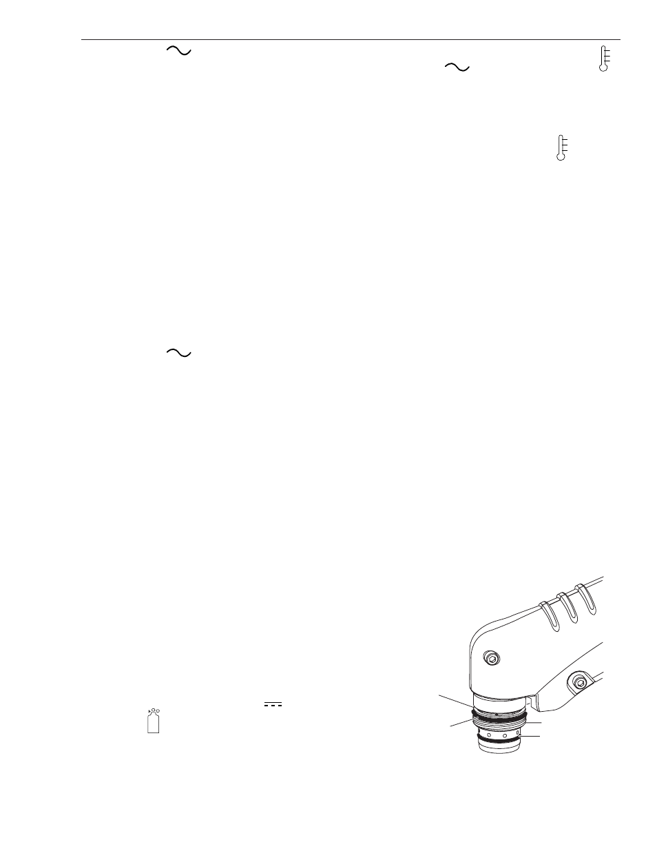
2. Upper O-ring on torch head is in wrong position.
a. Remove shield cup from torch; check position
of upper O-ring. Correct if necessary.
Lower O-Ring
Upper O-Ring
in Correct Groove
Upper Groove
with Vent Holes
Must Remain Open
Threads
Art # A-03640