Tweco Merlin 3000 Cutting Systems User Manual
Page 20
SERVICE
16
Manual 0-2475
• If 24vac is not present at J1 proceed to Step 10.
10. Place the RUN/SET/PURGE switch on the Control
Module to the RUN position.
11. Place the main power circuit breaker on front panel
of the Power Base Unit to OFF.
12. Remove the Torch Leads Extension Assembly from
the quick disconnect at the front panel of the Power
Base Unit.
13. Turn the main power circuit breaker on the front of
the Power Base Unit to ON.
14. Check for 24vac between pins 5 and 8 of the quick
disconnect signal connector.
• If not present, problem is in the Power Base Unit.
• If present, check for open in Torch Leads Extension
Assembly signal wires.
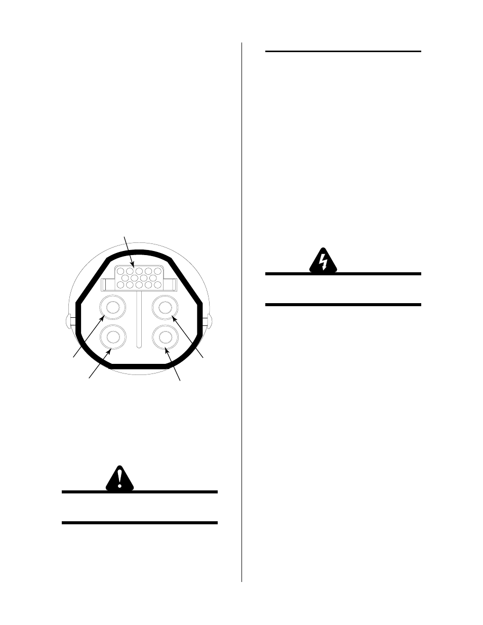
A-00809
1
2
3
4
5
6
7
8
9
10
11
12
13
14
Signal Connector
Torch (+)
Coolant Return
Secondary
Gas
Torch (-)
Figure 4-1 Signal Connector Pin Location
15. If 24vac was present at J1 from test in Step 5 or 9
place RUN/SET/PURGE to RUN position.
16. Press start after pre-flow and go through start se-
quence. PILOT and DC LEDs are ON.
WARNING
High voltage (300-400vdc) is present in Arc Starter
Box.
17. Measure between E1 (+) and E2 (-) on the Arc Starter
PC Board
• If voltage more than 220 vdc is present Arc Starter
PC Board is defective.
Note
A dirty or incorrect gap in spark gap could cause
the same problem. Gap should be 0.015 +/- 0.001"
and is not adjustable.
• If voltage is less than 220vdc proceed to Step 18.
18. In the Control Module measure the voltage between
W39 and W48 on the Pilot PC Board.
• If greater than 220vdc check for open connections
through the Umbilical Cable, Power Base Unit 2
and 4 pin disconnects, Torch Leads Extension As-
sembly, and Arc Starter Box input and output dis-
connects.
• If less than 220vdc refer to the Control/Power Mod-
ule Operating Manual 0-2473, Section 5.03 Trouble-
shooting, for low output volts.
B. Fault Isolation for Merlin 3000 Cutting
Systems
WARNING
High voltage may be present in the Arc Starter
Box.
The following two things are needed for the spark gap to
fire in the Arc Starter Box:
• 24 VAC bias voltage
The 24 VAC should be present anytime the Power
Supply is turned ON. Refer to Appendix II, 24
VAC Wiring Block Diagram.
• Greater than 220 VDC Power Supply output
The Power Supply DC output should be grearter
than 220 VDC when the Power Supply is activated
and the DC and PILOT LED's are ON. The volt-
age will be present across the torch tip (+) and elec-
trode (-).
The following procedure is to isolate the faulty assembly
to the Arc Starter PC Board, Power Supply, Torch, Torch
Leads, or Torch Leads Extension Assembly
1. To remove the voltage remove start signal from Power
Supply.
2. Place RUN/PURGE/SET in SET or PURGE position.
3. Power Supply DC and PILOT LEDs are OFF.
4. Remove cover from Arc Starter Box.
5. On the Arc Starter PC Board locate the red LED indi-
cator. When the indicator is ON the 24 VAC between
J1-1 and J1-3 is present to the Arc Starter PC Board.