Thermostat wiring, Mounted on wallboard, Fan cooling – tekmar 540 Thermostat Installation User Manual
Page 4: Gy r, Stud, Thermostat base wall, Tn4 c w r
4 of 28
© 2011
D 540 - 12/11
If a switch box was not used, mount the
thermostat directly to the wall.
Feed the wiring through the openings in
the back of the thermostat.
Use screws in the screw holes to fasten the
thermostat to the wall. At least one of the
screws should enter a wall stud or similar
rigid material.
•
•
Stud
2
3
/
8
”
(60 mm)
screwhole
2
3
/
8
”
(60 mm)
screwhole
Thermostat
Base
Wall
Mounted on wallboard
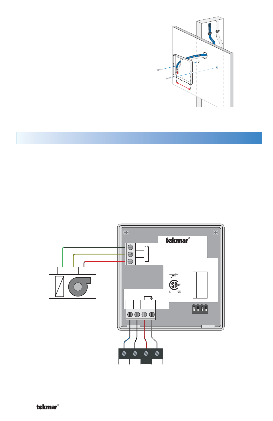
Thermostat Wiring
The thermostat operates a single heating system zone together with a cooling
system and fan.
Connect tN4, C, R, and W terminals on the thermostat to the tN4, C, R and W terminals
on the tN4 Wiring Center or Zone Manager.
Connect the Rc, Y and G terminals on the thermostat to the R, Y and G terminals
on the cooling equipment.
1
2
3
4
tN4 Wiring Center
or
tN4 Zone Manager
Cooling Equipment
1 Stage
Cooling
1 Stage
Fan
G
Y
R
D
X
Fan
Cooling
tN4
C
W
R
1 2 3 4
tNt 540
54
0
One Stage Heat /
One Stage Cool / One Fan
Mmm YYYY
Lo
t # 1
23
45
Mee
ts Class B:
Canadian ICES FCC P
ar
t 1
5
Power:
24 V ±10% 50/60 Hz 1.8 VA
56 VA fully loaded
Relays:
24 V (ac) 2 A
10
01
-0
1
tN4
1
C
2
R
3
W
4
7
G
6
Y
5
Rc
Switch Se
ttings:
For instructions see brochure
Use at least 75°C conductors
Se
tback
Scene
Lock
No
t used
ON
No
t used
Unlock
Off
Off