Thermostat wiring, Testing the thermostat wiring, Mounted on wallboard – tekmar 537 Thermostat Installation User Manual
Page 4: Testing the power
4 of 20
© 2011
D 537 - 12/11
If a switch box was not used, mount the
thermostat directly to the wall.
Feed the wiring through the openings in
the back of the thermostat.
Use screws in the screw holes to fasten the
thermostat to the wall. At least one of the
screws should enter a wall stud or similar
rigid material.
•
•
Stud
2
3
/
8
”
(60 mm)
screwhole
2
3
/
8
”
(60 mm)
screwhole
Thermostat
Base
Wall
Mounted on wallboard
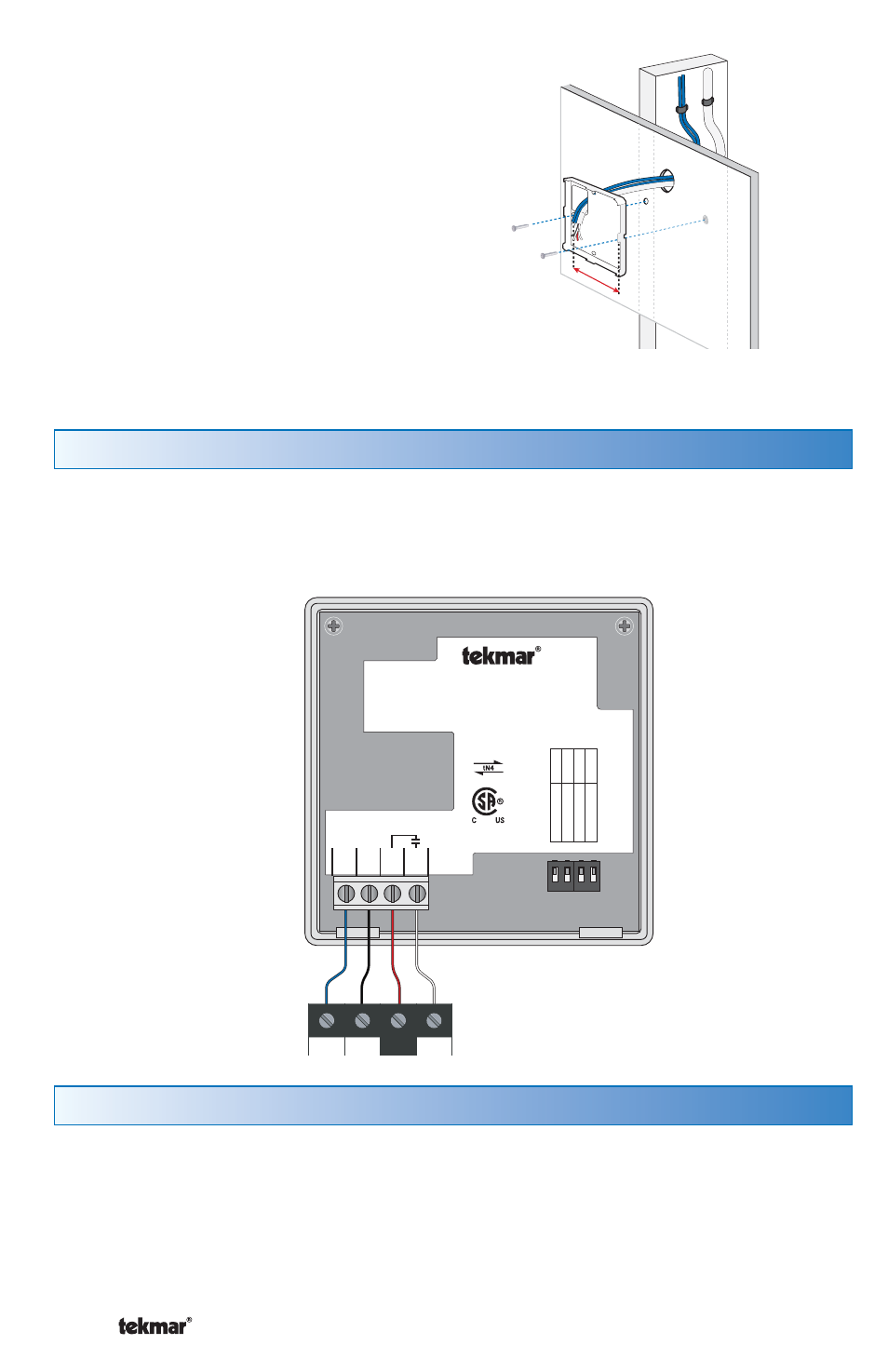
Thermostat Wiring
The thermostat operates a single heating system zone.
Connect tN4, C, R, and W terminals on the thermostat to the tN4, C, R and W terminals
on the tN4 Wiring Center or Zone Manager.
1
2
3
4
tN4 Wiring Center
or
tN4 Zone Manager
tN4
C
W
R
1 2 3 4
tNt 537
537
One Stage Heat
Mmm YYYY
Lo
t 1
23
45
Mee
ts Class B:
Canadian ICES FCC P
ar
t 1
5
Power: 24 V ±10% 50/60 Hz 1.8 VA
56 VA fully loaded
Relay: 24 V (ac) 2 A
10
01
-0
2
tN4
1
C
2
R
3
W
4
Switch Se
ttings:
For instructions see brochure
Use at least 75°C conductors
Se
tback
Scene
Lock
ON
Unlock
Off
Off
No
t used
No
t used
Testing the Thermostat Wiring
Testing the Power
---------------------------------------------------
---------------------------------------------------
1. Remove the front cover from the thermostat.
2. Use an electrical test meter to measure (ac) voltage between the R and C
terminals. The reading should be 24 V (ac) +/– 10%.
3. Install the front cover.