tekmar 368 Zone Control User Manual
Page 7
7
(12) terminal on the last 368 in the chain can be connected to the
Zo In terminal on a
tekmar reset control.
Note
The wires from the Zone Control are polarity sensitive. The system will not
operate if the wires are reversed.
UnOccupied Switch
If an external timer or switch is used, connect the two wires from the external dry
contact switch to the
UnO Sw — Com Sen (11 and 13) terminals. When these
terminals short together, the control registers an UnOccupied signal.
Note
If an external switch is closed between the terminals
UnO Sw — Com Sen
(11 and 13), the 24 hr. Timer is disabled and the Optimum Start / Stop
information is lost. It is recommended that either the 24 hr. Timer or an
external timer / switch is used, not both at the same time.
One Stage RTU and Indoor Sensor Connections
RTUs and Indoor Sensors provide indoor temperature feedback to the control.
Common block for
RTU 1 and RTU 2
• If the common block is used for a single One Stage heating zone, connect the RTU
or Indoor Sensor to terminals
Com Sen — RTU 1 (5 and 6).
• If the common block is used for 2 One Stage heating zones, connect one RTU or
Indoor Sensor to the
Com Sen — RTU 1 (5 and 6) terminals and connect the other
RTU or Indoor Sensor to the
Com Sen — RTU 2 (5 and 7) terminals.
Common block for
RTU 3 and RTU 4
• If the common block is used for a single One Stage heating zone, connect the RTU
or Indoor Sensor to terminals
Com Sen — RTU 3 (8 and 9).
• If the common block is used for 2 One Stage heating zones, connect one RTU to
the
Com Sen — RTU 3 (8 and 9) terminals and connect the other RTU to the Com
Sen — RTU 4 (8 and 10) terminals.
Two Stage RTU and Indoor Sensor Connections
Common Block for
RTU 1 and RTU 2
• If the common block is used for a Two Stage heating zone, connect the RTU or
Indoor Sensor to terminals
Com Sen — RTU 2 (5 and 7).
Common Block for
RTU 3 and RTU 4
• If the common block is used for a Two Stage heating zone, connect the RTU or
Indoor Sensor to terminals
Com Sen — RTU 4 (8 and 10).
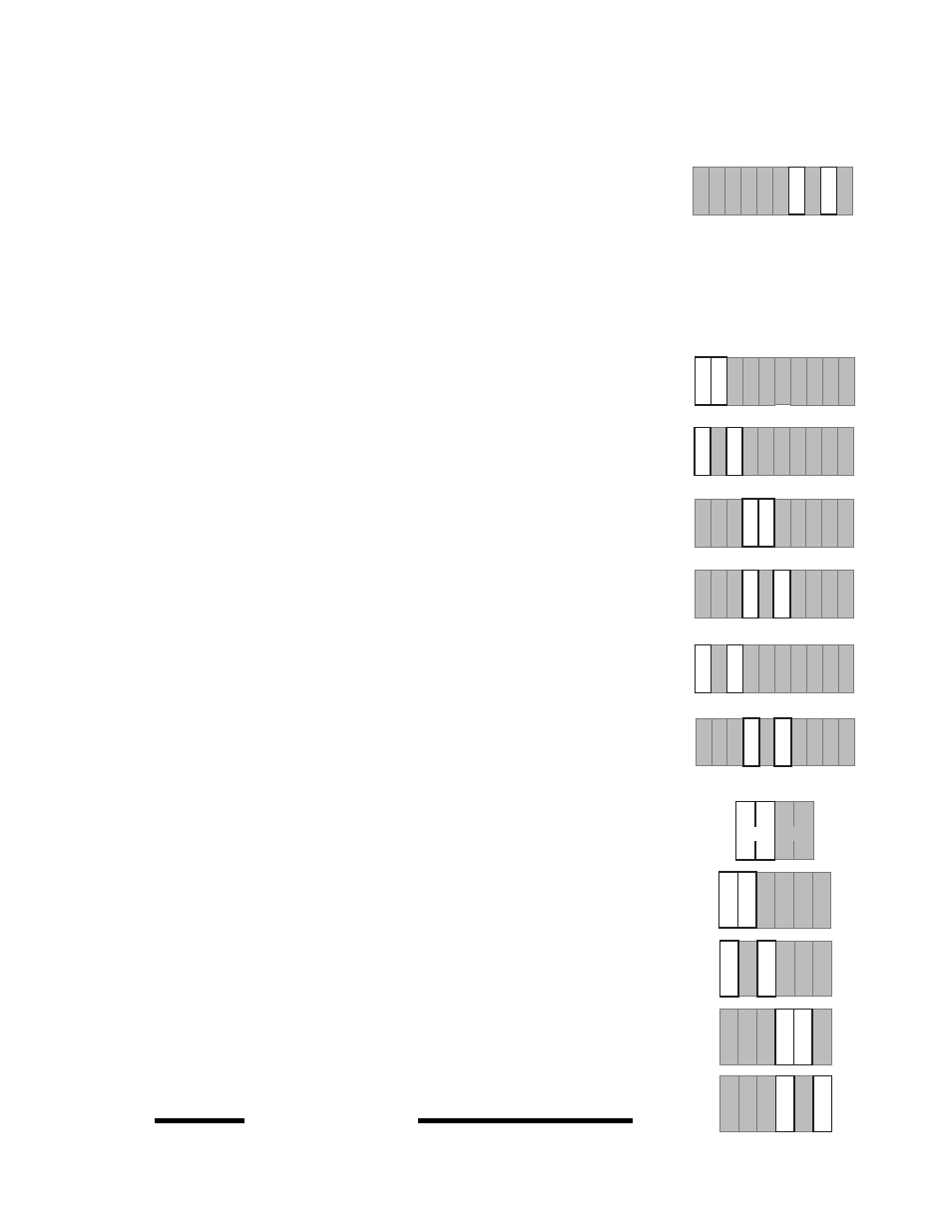
Output Connections
System Pump
Connect the live (L) side of the 120 V (ac) pump circuit through the
System Pmp —
System Pmp (1 and 2) terminals. The control closes a dry relay contact between these
terminals when operation of the system pump is required.
Zone Pumps and Valves
Note
Do not connect a zone pump and zone valve circuit to the same
Com terminal.
• If relay
1 is used, connect the zone pump or zone valve circuit to the Com 1-2 — 1
(15 and 16) terminals on the control.
• If relay
2 is used, connect the zone pump or zone valve circuit to the Com 1-2 — 2
(15 and 17) terminals on the control.
• If relay
3 is used, connect the zone pump or zone valve circuit to the Com 3-4 — 3
(18 and 19) terminals on the control.
• If relay
4 is used, connect the zone pump or zone valve circuit to the Com 3-4 — 4
(18 and 20) terminals on the control.
STEP FIVE
TESTING THE WIRING
Each terminal block must be unplugged from its header on the control before power
is applied for testing. Pull straight down to unplug the terminal block.
Com
Sen
UnO
Sw
5 6
RTU
1
12
11
13
Com
Sen
14
Zo
In
Zo
Out
RTU
2
7
RTU
3
9
RTU
4
10
8
Com
Sen
15 16 17
1
18
19
3
4
20
Com
1-2
2
Com
3-4
15 16
17
1
18 19
3
4
20
Com
1-2
2
Com
3-4
15
16
17
1
18 19
3
4
20
Com
1-2
2
Com
3-4
15 16 17
1
18 19
3
4
20
Com
1-2
2
Com
3-4
3
1 2
N
L
Pmp
4
Power
Pmp
System
Com
Sen
UnO
Sw
5 6
RTU
1
12
11
13
Com
Sen
14
Zo
In
Zo
Out
RTU
2
7
RTU
3
9
RTU
4
10
8
Com
Sen
Com
Sen
UnO
Sw
5
6
RTU
1
12
11
13
Com
Sen
14
Zo
In
Zo
Out
RTU
2
7
RTU
3
9
RTU
4
10
8
Com
Sen
Com
Sen
UnO
Sw
5 6
RTU
1
12
11
13
Com
Sen
14
Zo
In
Zo
Out
RTU
2
7
RTU
3
9
RTU
4
10
8
Com
Sen
Com
Sen
UnO
Sw
5 6
RTU
1
12
11
13
Com
Sen
14
Zo
In
Zo
Out
RTU
2
7
RTU
3
9
RTU
4
10
8
Com
Sen
Com
Sen
UnO
Sw
5 6
RTU
1
12
11
13
Com
Sen
14
Zo
In
Zo
Out
RTU
2
7
RTU
3
9
RTU
4
10
8
Com
Sen
Com
Sen
UnO
Sw
5
6
RTU
1
12
11
13
Com
Sen
14
Zo
In
Zo
Out
RTU
2
7
RTU
3
9
RTU
4
10
8
Com
Sen